20
MYDENS 60
COSMOGAS
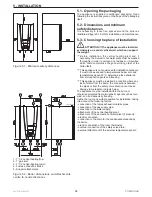
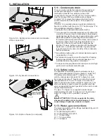
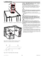
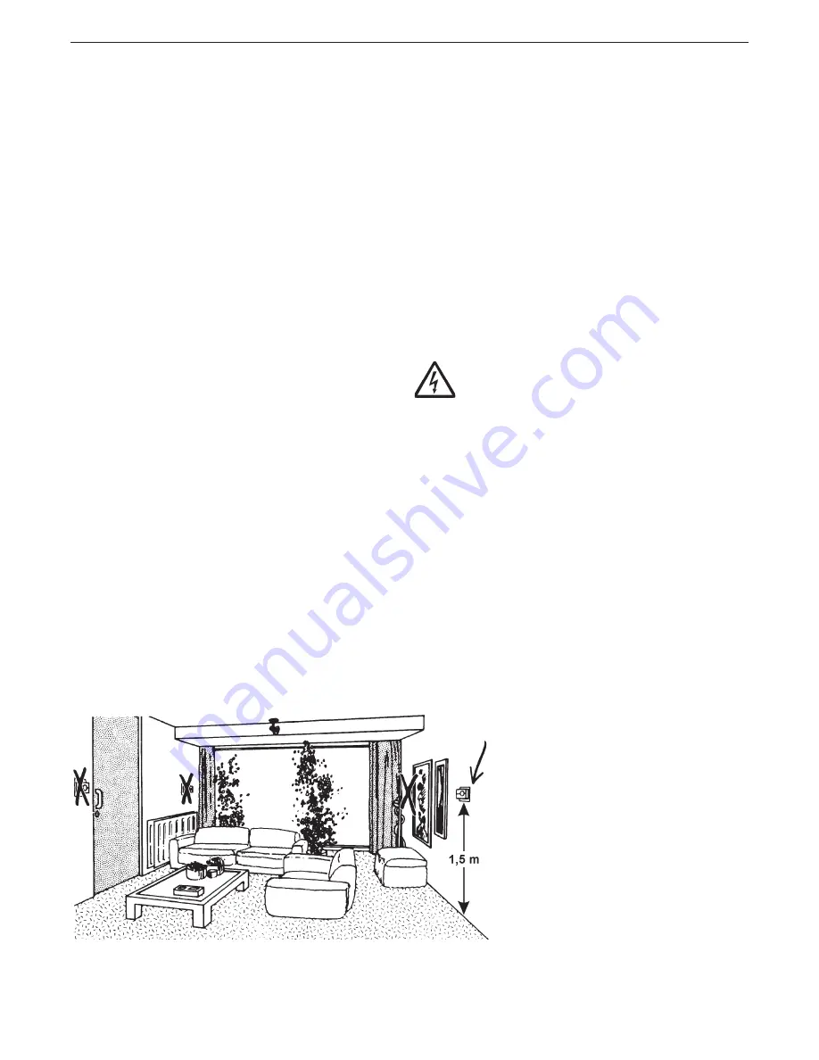
Figure 5.8 - Correct positioning of the room
thermostat/chronothermostat
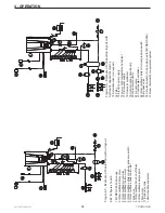
5.14.1 - Power supply cable connection
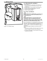
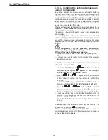
Proceed as follows to connect the power supply cable (refer
to figure 5.7):
1.- use a three-polar cable with double isolation, with
minimum section of 1.5 mm²;
2.- remove the casing from the appliance following the
relevant instructions in chapter 8.2;
3.- rotate the panel “A” towards the front of the boiler;
4.- operate on the flaps “C” and open the lid “B” as indicated
by the arrow;
5.- lay the power supply cable through the fairlead in
proximity of the contacts “L1”, “N” and earth symbol;
6.- strip the cable making sure that the earth wire (yellow/
green) is kept 20 mm longer than the other two;
7.- connect the yellow-green cable to the earth clamp (see
symbol);
8.- connect the brown cable (Phase) to the clamp L1;
9.- connect the blue cable (Neutral) to the clamp N.
5.14.2 - Choice of the room thermostat/
chronothermostat
The boiler is set-up to operate with any room thermostat
or chronothermostat, which has the contact to which the
cables coming from the boiler are to be connected, with the
following features:
- open/closed (ON/OFF);
- potential-free (not powered);
- closing when there is a request for heat;
- 24Vac, 1A electrical feature
5.14.3 - Connecting the room thermostat/
chronothermostat
Install the room thermostat in a place in the house where
the temperature is the most characteristic of the home
and however in an area that is not subjected to repeated
temperature changes, away from windows or doors which
open directly to the outside (see figure 5.8).
Proceed as follows to connect the room thermostat cable
(refer to figure 5.7):
1.- use a bi-polar cable with minimum section of 1.5mm²,
which goes from the boiler to the room thermostat/
chronothermostat. The maximum length allowed is 20
metres. For lengths exceeding 100 metres, use a shielded
cable with shield earthing;
2.- remove the casing from the appliance following the
relevant instructions in chapter 8.2;
3.- lay the electric cable through the fairlead in proximity of
the “TA” contacts;
4.- use a free fairlead, not used by other wires;
5.- strip the cable;
6.- connect the two ends of the cable to the “TA” clamps
(see figure 5.7).
ATTENTION !!! As the room thermostat/
chronothermostat cables are subjected to very low safety
voltage (25Vdc), they must flow in wires different from the
230 Vac power supplies.
5 - INSTALLATION

