28
MYDENS 60
COSMOGAS
5 - INSTALLATION
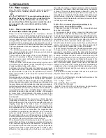
B
C
A
020008.01.013
5.16.5 - “80/125PP vertical coaxial” System
(polypropylene) (C13; C33)
The appliance is supplied as per standard without fittings
for the connection of the fumes exhaust/air intake. To
connect it to a 80/125 vertical coaxial system, the relevant
kit must be requested and must be installed as in figure
5.15.
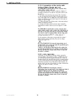
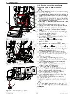
ATTENTION !!! Scrupulously follow the installation
phases of the coaxial pipe as illustrated in figure 5.17. In
particular:
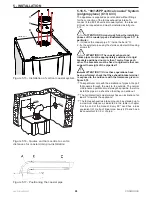
1.- introduce the coaxial pipe “C” inside the bend “A”;
2.- fix the external pipe using the stainless steel self-threading
screws “B”.
ATTENTION !!! The coaxial exhaust and
intake pipes must be appropriately sustained via rigid
brackets positioned no more than 1 metre from each
other. The brackets must be fixed to rigid walls that can
support the weight of the pipe itself.
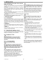
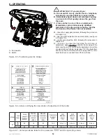
ATTENTION !!! Once these operations have
been performed, check that the exhaust/intake terminal
is exposed to the outdoors with the tolerances given in
figure 5.18
Take particular care with the installation of pipes in the part
that passes through the wall to the outside. The normal
maintenance operations must always be possible, therefore
install the pipes in a sheath so that they can slide out.
The horizontal tracts must always have an inclination of at
least 2% towards the appliance.
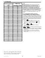
The fumes exhaust/air intake pipe can be extended up to
a maximum distance as indicated in the table in chapter
9 at the end of the manual. Every 90° bend has a loss
equivalent to 1 metre of linear pipe. Every 45° bend has a
loss equivalent to 0.5 m of pipe.
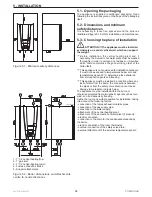
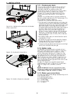
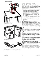
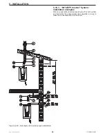
Figure 5.15 - Installation of vertical coaxial system
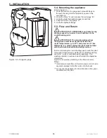
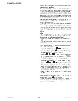
Figure 5.16 - Quotes and hole centre to centre
distances for coaxial drain pre-installation
Figure 5.17 - Positioning the coaxial pipe

