background image

2

3

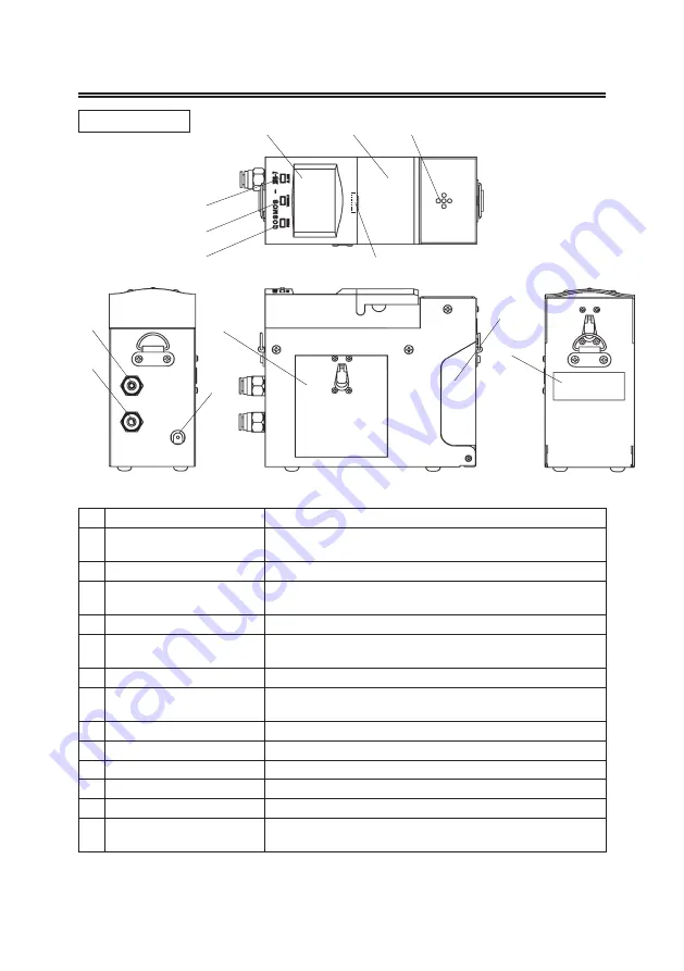
4  Component Names and Functions

No

Name

Function

Power lamp (green)

Flashes during the warm up period after the power is turned 

ON and remains lit during operation.

Trouble lamp (yellow)

Flashes when an error occurs.

Alarm lamp (red)

Flashes when the detected gas concentration reaches the 

alarm point.

LCD display

Indicates gas concentration and other information.

Key switch cover

Lightly pull the cover toward you to open it and access the key 

switches.

Buzzer speaker

Gas inlet

Sampled gas aspiration inlet. (6 dia.) Attaches to the gas inlet 

tube.

Gas outlet

Exhaust outlet for sampled gas (6 dia.)

Adapter connector

Connects to the 100-VAC/6-VDC adapter plug.

Battery cover

Lift the snap lock and open the cover to insert batteries.

Sensor cover

Lift the snap lock and open the cover to insert the sensor unit.

Sensor window

Used to check the sensor unit that is installed.

LED (red)

(Battery check)

Lit if the key switch cover is open with the Gas Detector turned 

OFF, when batteries are inserted, or when batteries are low.

Main Unit

④               ⑤         ⑥

2

3

●  Observe the following precautions for the storage environment and method 

of storing the Gas Detector.

WARNING

Do not store the Gas Detector for long periods in locations with high temperatures or 

high humidity. Otherwise, the performance of the Detector may be impaired.

CAUTION

Do not subject the Gas Detector to sudden changes in temperature or humidity. 

Otherwise, the performance of the Detector may be impaired.

CAUTION

If the Gas Detector is not to be used for a long time, remove the batteries before 

storing it.

2  Contents of This Package

The following components are included with the Gas Detector. Ensure that all components are 

present before attempting to use the Detector.

Gas Detector …………………………… 1

Filters ……………………………………  2

Shoulder strap  …………………………  1

AA alkaline batteries……………………  4

Gas inlet tube…………………………… 1

Inspection results………………………  1

Instruction manual……………………… 1

3  Sensor Units

Model

Detected gases

FS

Alarm setting

1st level

2nd level

XDS-7NH

NH

3

Ammonia

100 ppm

12 ppm

25 ppm

XDS-7SH

SiH

4

Silane

25 ppm

2.5 ppm

5 ppm

XDS-7DC

SiH

2

Cl

2

Dichlorosilane

25 ppm

2.5 ppm

5 ppm

XDS-7AH

AsH

3

Arsine

250 ppb

25 ppb

50 ppb

XDS-7PH 

PH

3

Phosphine

1 ppm

0.15 ppm

0.3 ppm

XDS-7BH 

B

2

H

6

Diborane

500 ppb

50 ppb

100 ppb

XDS-7SE 

H

2

Se

Hydrogen selenide

250 ppb

25 ppb

50 ppb

XDS7GH 

GeH

4

Germane

1 ppm

0.1 ppm

0.2 ppm

XDS-7CL

Cl

2

Chlorine

5 ppm

0.25 ppm

0.5 ppm

XDS-7CF 

ClF

3

Chlorine trifluoride

1 ppm

0.05 ppm

0.1 ppm

XDS-7HC 

HCl

Hydrogen chloride

25 ppm

2.5 ppm

5 ppm

XDS-7HF 

HF

Hydrogen fluoride

10 ppm

1.5 ppm

3 ppm

XDS-7HB

HBr

Hydrogen bromide

10 ppm

1.5 ppm

3 ppm

XDS-7NO 

NO

Nitrogen monoxide

100 ppm

12 ppm

25 ppm

XDS-7HS 

H

2

S

Hydrogen sulfide

50 ppm

5 ppm

10 ppm

XDS-7CO 

CO

Carbon monoxide

250 ppm

12.5 ppm

25 ppm

XDS-7DS 

Si

2

H

6

Disilane

25 ppm

2.5 ppm

5 ppm

XDS-7F2 

F

2

Fluorine

5 ppm

0.5 ppm

1 ppm

XDS-7OZ 

O

3

Ozone

1 ppm

0.05 ppm

0.1 ppm

Contact an authorized representative of New Cosmos regarding other detectable gases not listed in the 

table.

Summary of Contents for XPS-7

Page 1: ...his manual Instruction manual No XPS 7T 10 Semiconductor Plant Gas Detector XPS 7 Instruction Manual Store this Instruction manual in a convenient location and consult it whenever necessary Operate th...

Page 2: ...ing Procedure 6 5 1 Inserting Batteries 6 5 2 Installing the Sensor Unit 7 5 3 Turning the Gas Detector ON 8 5 4 Detection 8 5 5 Ending Detection 8 6 Logger Function 9 7 Replacing the Filter 10 8 Dail...

Page 3: ...ath WARNING Indicates a potentially hazardous situation that if not avoided could re sult in serious injury or death CAUTION Indicates a potentially hazardous situation that if not avoided could re su...

Page 4: ...es FS Alarm setting 1st level 2nd level XDS 7NH NH3 Ammonia 100 ppm 12 ppm 25 ppm XDS 7SH SiH4 Silane 25 ppm 2 5 ppm 5 ppm XDS 7DC SiH2Cl2 Dichlorosilane 25 ppm 2 5 ppm 5 ppm XDS 7AH AsH3 Arsine 250 p...

Page 5: ...to open it and access the key switches Buzzer speaker Gas inlet Sampled gas aspiration inlet 6 dia Attaches to the gas inlet tube Gas outlet Exhaust outlet for sampled gas 6 dia Adapter connector Con...

Page 6: ...ecial command switch Used with the logger function UP DOWN switches Used to set the start time and other logger function settings Key Switches LCD Display Log indicator Lit when the log function is op...

Page 7: ...is attached make sure that it will not pull out Removing Press in the release ring on the coupling and simultaneously pull out the gas inlet tube Attaching Removing Gas Inlet Tube Filter case Contains...

Page 8: ...AA alkaline batteries provided and make sure they are inserted according to the polarity indicated in the battery compartment Close the battery cover WARNING Replace all four batteries at the same tim...

Page 9: ...power to the sensor unit A sensor unit that does not have power to it cannot detect gases and may cause the sensor trouble indicator to light A sensor unit installed in the Gas Detector is powered eve...

Page 10: ...after a power failure 5 4 Detection Place the gas sampling pipe near the target detection area When the unit detects gas the concentration of the detected gas is displayed If the detected gas concentr...

Page 11: ...e log data to a personal computer Press the DOWN switch once in RUN mode LOG will be displayed on the lower right corner of the LCD display and the log start time can be entered Press the SPECIAL COMM...

Page 12: ...re factory adjustments that are not available for user application 7 Replacing the Filter Twist the lter holder with detection probe to open it Use a pair of tweezers to remove the O ring and filter I...

Page 13: ...age 6 The batteries are low Replace the batteries The sensor unit is not installed Install a sensor unit Page 7 Abnormal drop in the ow rate The lter is clogged Replace the lter with a new one Page 10...

Page 14: ...After examination of allegedly defective product return to New Cosmos with freight prepaid should the product fail to conform to this warranty customer s only remedy and New Cosmos s only obligation s...

Page 15: ...2 hours of continuous operation at 20 with alkaline batteries and no alarms Operating temperature range 0 to 40 Dimensions W 62 x H 150 x D 128 mm projected portions excluded Mass Approx 1 3 kg Approv...

Page 16: ...Distributor Manufacturer New Cosmos Electric Co Ltd 2 5 4 Mitsuya naka Yodogawa ku Osaka 532 0036 Japan URL http www newcosmos global com XPS 7 09 T XPS 7T 10 2008 100...

Reviews: