background image

One-Channel Video Receiver 


15 

Appendix 


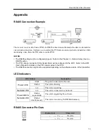
RS485 Connection Example 


The receiver receives data from a DVR via RS485 connection and transmits the data to a transmitter 
via network connection.  It allows you to control the PTZ camera connected to the transmitter while 
monitoring video from the PTZ camera on the DVR. 
 

NOTES: 

  The RS485 setting must be configured properly.  Refer to the 

Chapter 3 – Remote Setup

Device

 – 

RS485

 section. 

  The PTZ camera connected to the transmitter must be configured in the DVR.  Refer to the DVR 

User’s Manual for details on the PTZ camera setup in the DVR. 

  The RS485 connection might not be supported depending on the software version of the transmitter. 


LED Indicators 


LED Status 

Description 

Power LED


Unlit 

No power connected to the unit. 

Flicker 

The unit is booting. 

Lit 

The unit is operating. 

Network LED


Lit 

The unit is connected to a network. 

Power LED & 

Network LED 

Flicker 

sequentially 

The unit is upgrading the software. 

Flicker 

simultaneously

The unit is recovering NAND flash memory. 


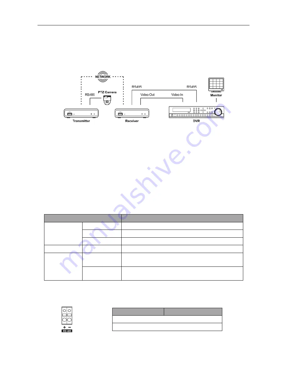
RS485 Connector Pin Outs 


Master Unit


Slave Unit


                + 

   To   

TX+/RX+ 

                – 

   To   

TX-/RX- 


Summary of Contents for CR1000INR

Page 1: ......

Page 2: ......

Page 3: ...f publication We are not responsible for any problems resulting from the use thereof The information contained herein is subject to change without notice Revisions or new editions to this publication may be issued to incorporate such changes The software included in this product contains some Open Sources You may obtain the complete corresponding source code from us See the Open Source Guide on th...

Page 4: ...atteries according to the instructions 18 Tmra A manufacturer s maximum recommended ambient temperature Tmra for the equipment must be specified so that the customer and installer may determine a suitable maximum operating environment for the equipment 19 Elevated Operating Ambient Temperature If installed in a closed or multi unit rack assembly the operating ambient temperature of the rack enviro...

Page 5: ...3 1 Quick Setup 5 3 2 System 6 General 6 Date Time 6 3 3 Network 7 IP Address 7 DVRNS 7 Port 8 Security 8 3 4 Video 9 Camera List 9 Display 10 3 5 Device 10 Audio 10 RS485 11 3 6 XUI 11 Setting 11 Chapter 4 Live Monitoring 13 4 1 Video Monitoring 13 4 2 Audio Communication 13 4 3 Setup 14 4 4 PTZ Control 14 Appendix 15 RS485 Connection Example 15 LED Indicators 15 RS485 Connector Pin Outs 15 Troub...

Page 6: ...User s Manual iv ...

Page 7: ...m This receiver offers the following features BNC composite or VGA video output automatic detection for VGA monitor Decompression algorithm for H 264 MPEG 4 and M JPEG Two way audio communication Convenient firmware upgrades via either the USB port or the network Firmware duplication and autorecovery functions to enhance system stability Managing multiple receivers via Ethernet connections XUI fun...

Page 8: ...User s Manual 2 1 3 Typical Applications ...

Page 9: ...isplays network connection status Refer to Appendix A LED Indicators for details Power LED Displays system operating status Refer to Appendix A LED Indicators for details Factory Reset This switch will only be used on the rare occasions that you want to return all the settings to the original factory settings CAUTION When performing a Factory Reset you will lose any settings you have saved Disconn...

Page 10: ...er 5 VDC 0 8A The receiver starts booting as soon as power is applied NOTES It is possible that the receiver will not detect a VGA monitor automatically if the connected VGA monitor does not support the auto detect function In this situation switch the video output to VGA out See Chapter 3 Remote Setup 3 4 Video Display for details on switching video output Camera and audio surveillance may be pro...

Page 11: ...e Setup screen by selecting a receiver clicking the right mouse button and selecting Remote Setup on the Main screen Clicking a menu in the left of the Remote Setup screen displays the current settings for that menu on the right side of the screen Clicking submenus under each menu allows you to change the settings Clicking the OK button closes the Remote Setup screen and applies the changes 3 1 Qu...

Page 12: ...le You can select whether or not network settings except the DVRNS setting will be included when the setup is applied Refer to the Network menu for details about the network settings Export Setup Click to save the current receiver settings as a dat file format A setup screen appears allowing you to name the setup file NOTE Do NOT check the Include Network Setup box when the network settings of the...

Page 13: ...ame of the server can be used instead of the IP address when the DVRNS time server and SMTP servers are set up Ask your Internet service provider for the IP Address of the DNS Server NOTES Ask your network provider for details about the network connection type and connection information for the receiver If the receiver is configured for a DHCP or ADSL network it is best to use the DVRNS function b...

Page 14: ...erver during the IP Address setup When using a NAT Network Address Translation device refer to the NAT manufacturer s instructions for the proper network settings The receiver s name you entered in the DVR Name field should be checked by clicking the Check button otherwise the DVRNS changes will not be saved When entering no name or a name already registered on the DVRNS server an error message di...

Page 15: ...click the button and register the camera manually by entering the IP address of the video input device Add Click to register a camera manually by entering the IP address of a video input device if the device is a DVR or when the device is not networked Camera Setup Enter a camera name and the IP address and select a desired camera number ID If the device supports more than one audio input select a...

Page 16: ...unit is connected to a network via Ethernet Freeze Sequence The icon is displayed while in the freeze mode No Title The number and title of the connected camera are displayed Event Event icons are displayed when the events are detected Motion detection Alarm in NO VIDEO Video loss BLIND VIDEO Video blind PTZ The icon is displayed when the connected camera is a PTZ camera Audio The speaker or micro...

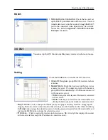
Page 17: ...ceivers with the same group ID will be controlled by a USB mouse connected to the master receiver Table Arrange the table layout of the monitor connected to the receiver Master Selecting a monitor from the monitor table and clicking the button sets up the monitor as a master monitor Merge Divide Click to change the table layout by merging or dividing monitors Dragging and dropping the mouse cursor...

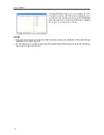
Page 18: ...P Address field in the right box You can enter the IP address manually if a receiver is not displayed in the list NOTES A receiver cannot share a mouse when the receiver is not set up to enable the XUI function though registered on a master receiver You should set up as a master receiver only the receiver that a USB mouse is connected to Otherwise the mouse will not work properly ...

Page 19: ...era when the video input device to which the camera is connected is not networked Freeze Mode Selecting Freeze from the monitoring menu freezes the current image on the screen Click the left mouse button on the screen or select Freeze again from the monitoring menu to release the Freeze mode While in the Freeze mode the icon is displayed in the bottom left corner of the screen if Freeze is selecte...

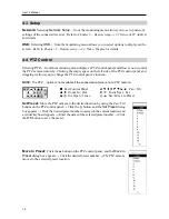
Page 20: ...el and dragging it allows you to change the PTZ control panel s location NOTE The PTZ option is not available if the connected camera is not a PTZ camera Exit Control Panel Pan Tilt Zoom In Out Focus Near Far Iris Open Close Set Move to Preset Set Preset Move the PTZ camera to the desired location by using the Pan Tilt buttons on the PTZ control panel Click the button and the Set Preset dialog box...

Page 21: ...a connected to the transmitter must be configured in the DVR Refer to the DVR User s Manual for details on the PTZ camera setup in the DVR The RS485 connection might not be supported depending on the software version of the transmitter LED Indicators LED Status Description Power LED Unlit No power connected to the unit Flicker The unit is booting Lit The unit is operating Network LED Lit The unit ...

Page 22: ...ted Switch the video output mode to VGA if the connected VGA monitor does not support the auto detect function Refer to Chapter 3 Remote Setup 3 4 Video Display for details on video output mode setup The mouse controlling multiple receivers does not work properly Check XUI settings of each receiver that shares a mouse The XUI function must be enabled and the XUI group ID of all receivers must be t...

Page 23: ...e in or Microphone Audio Output 1 line out Use a Y connector to connect audio in white and out red CONNECTORS Video Output BNC or VGA Audio In Out RCA Y connector Ethernet Port RJ 45 RS485 Serial Port Terminal block USB Port 2 0 1 on front panel GENERAL Dimensions W x H x D 4 7 x 1 1 x 4 3 119mm x 29mm x 108mm Shipping Dimensions W x H x D 10 4 x 4 1 x 7 5 265mm x 105mm x 190mm Unit Weight 0 64 lb...

Reviews: