
One-Channel Video Transmitter
V2.2 25
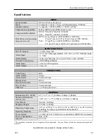
Specifications
VIDEO
Signal Format
NTSC or PAL (auto detect)
Input
Composite: 1 input, 1 Vp-p, switch-terminating, 75 Ohms
Input Resolution
Composite: 720x480 (NTSC), 720x576 (PAL)
Compression Algorithm
H.264, MPEG-4, M-JPEG (Four levels)
Compression Resolution
NTSC: 704x480, 704x240, 352x240
PAL:
704x576, 704x288, 352x288
Frame Rate
(Live/Recording)
(images per second)
NTSC: 30 ips/30 ips @ 4CIF (MPEG-4, M-JPEG)
15 ips/15 ips @ 4CIF or 30 ips/0 ips @ 4CIF (H.264)
PAL: 25 ips/25 ips @ 4CIF (MPEG-4, M-JPEG)
12.5 ips/12.5 ips @ 4CIF or 25 ips/0 ips @ 4CIF (H.264)
INPUTS/OUTPUTS
DC 12V Output
12 VDC, Max. 6W
Alarm Input
1 TTL, NC/NO programmable, 2.4V (NC) or 0.3V (NO) threshold,
3.3 VDC
Alarm Output
1 relay out, NO only, 0.3A @ 125 VAC, 1A @ 30 VDC
Network Connectivity
10/100 Mbps Ethernet
Audio Input
1 line in or Microphone
Audio Output
1 line out
CONNECTORS
Video Input
BNC
Audio In/Out
Stereo
Alarm In/Out
Terminal block
Ethernet Port
RJ-45
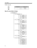
RS-485 Serial Port
Terminal block
DC 12V Out
Terminal block
USB Port
1 on front panel (2.0)
GENERAL
Dimensions (W x H x D)
4.7" x 1.1" x 4.3" (119mm x 29mm x 108mm)
Shipping Dimensions
(W x H x D)
10.4" x 4.1" x 7.5" (265mm x 105mm x 190mm)
Unit Weight
0.64 lbs. (0.29Kg)
Shipping Weight
2.78 lbs. (1.26Kg)
Operating Temperature
32°F to 122°F (0°C to 50°C) (32°F to 104°F (0°C to 40°C) when
installing by using a specialized rack mount kit*)
Operating Humidity
0% to 90%
Power Supply
12 VDC, 24 VAC, PoE (Power over Ethernet) (IEEE 802.3af, class0)
Power Consumption
Max. 13W
Approval FCC,
CE
*
The specialized rack mount kit is not supplied with the transmitter. Ask your dealer or distributor about purchasing the rack
mount kit.
Specifications are subject to change without notice.


