background image

Summary of Contents for CR1600ET

Page 1: ......

Page 2: ......

Page 3: ...NERATES USES AND CAN RADIATE RADIO FREQUENCY ENERGY AND IF NOT INSTALLED AND USED IN ACCORDANCE WITH THE INSTRUCTION MANUAL MAY CAUSE HARMFUL INTERFERENCE TO RADIO COMMUNICATIONS OPERATION OF THIS EQUIPMENT IN A RESIDENTIAL AREA IS LIKELY TO CAUSE HARMFUL INTERFERENCE IN WHICH CASE USERS WILL BE REQUIRED TO CORRECT THE INTERFERENCE AT THEIR OWN EXPENSE WARNING CHANGES OR MODIFICATIONS NOT EXPRESSL...

Page 4: ...g this equipment from the wall outlet and refer servicing to qualified service personnel under the following conditions A When the power supply cord or the plug has been damaged B If liquid is spilled or objects have fallen into the equipment C If the equipment has been exposed to rain or water D If the equipment does not operate normally by following the operating instructions adjust only those c...

Page 5: ...onnector 6 Chapter 3 Configuration 7 Front Panel Controls 7 Power LED 8 HDD LED 8 Alarm Out LED 8 Network LED 8 Clip Copy LED 8 Camera Buttons 8 PLAY PAUSE Button 9 Arrow Buttons 9 MENU CAMEO Button 9 PLAYBACK Button 9 ZOOM PTZ Button 9 DISPLAY SPOT Button 10 GROUP SEQUENCE Button 10 CLIP COPY Button 10 ALARM Button 10 PANIC Button 10 USB Port 10 ID Button on Remote Control 10 Bookmark Button on R...

Page 6: ...Installation Manual iv ...

Page 7: ...stry standard protocol IR Remote Control Self diagnostics with automatic notification including hard disk drive S M A R T protocol Technical Overview In addition to replacing both a time lapse VCR and a multiplexer in a security installation your DVR has many features that make it much more powerful and easier to use than even the most advanced VCR The DVR converts analog NTSC or PAL video to digi...

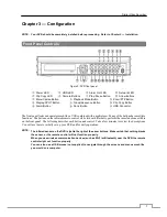
Page 8: ...be used to upgrade the system or copy video clips to external hard disk and flash drives Figure 1 Typical DVR installation NOTE This manual covers the 8 and 16 channel digital video recorders The DVRs are identical except for the number of cameras and alarms that can be connected and the number of cameras that can be displayed For simplicity the illustrations and descriptions in this manual refer ...

Page 9: ...tools are required to install the DVR Refer to the installation manuals for the other items that make up part of your system Figure 2 DVR rear panel Video Input Alarm Input Output RS485 Port RS232 Port eSATA Port Factory Reset Switch Video Out Network Port Audio In Out Power Cord Connector Your DVR can be used with either NTSC or PAL equipment NOTE You cannot mix NTSC and PAL equipment For example...

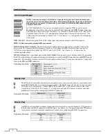
Page 10: ...trip press and hold the button and insert the wire in the hole below the button After releasing the button tug gently on the wire to make certain it is connected To disconnect a wire press and hold the button above the wire and pull out the wire AI 1 to 16 Alarm In You can use external devices to signal the DVR to react to events Mechanical or electrical switches can be wired to the AI Alarm In an...

Page 11: ...to the left of the HDMI connector 4 Hold the reset switch until the DVR s internal buzzer sounds twice 5 Release the reset switch All of the DVR s settings are now at the original settings it had when it left the factory Video Out An HDMI High Definition Multimedia Interface connector is provided so that you can use an HDMI monitor as your main monitor A VGA connector is provided so that you can u...

Page 12: ...ORDS SO THAT THEY ARE NOT A TRIPPING HAZARD MAKE CERTAIN THE POWER CORD WILL NOT BE PINCHED OR ABRADED BY FURNITURE DO NOT INSTALL POWER CORDS UNDER RUGS OR CARPET THE POWER CORD HAS A GROUNDING PIN IF YOUR POWER OUTLET DOES NOT HAVE A GROUNDING PIN RECEPTACLE DO NOT MODIFY THE PLUG DO NOT OVERLOAD THE CIRCUIT BY PLUGGING TOO MANY DEVICES IN TO ONE CIRCUIT Your DVR can record audio from up to four...

Page 13: ...uttons have multiple functions The buttons on the infrared remote control while laid out differently perform the same functions as those on the front panel The following describes each button and control Take a few minutes to review the descriptions You will use these to initially set up your DVR and for daily operations NOTE The infrared sensor on the DVR is just to the right of the arrow buttons...

Page 14: ...ower LED is lit when the unit is On HDD LED The HDD LED flickers when the DVR is recording or searching video on the hard disk drive Alarm Out LED The Alarm Out LED is lit when alarm output or internal buzzer is activated Network LED The Network LED is lit when the unit is connected to a network via Ethernet Clip Copy LED The Clip Copy LED is lit when the DVR is clip copying Camera Buttons Pressin...

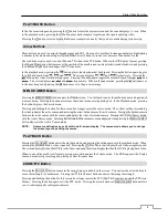
Page 15: ...log box In the Playback mode pressing the button displays the Search menu Pressing and holding the button for three seconds or longer enters the cameo mode The yellow outline surrounding the video indicates the active cameo and pressing the arrow buttons moves the active cameo Pressing the desired camera button in the active cameo edits the cameo and displays the video of selected camera Pressing ...

Page 16: ...rovided to connect external hard disk or flash drives for video clip copying or system upgrades Position external drives close enough to the DVR so that you can make the cable connections usually less than 6 feet Use the USB cable provided with the hard disk drive to connect it to the DVR A USB mouse not supplied can be connected to one of the ports You can use the mouse to navigate through the sc...

Page 17: ...alid package 10 Database has been changed 300 Remote connection failed 11 Appending failed 301 Remote network error 12 Bad sector 302 Remote upgrade is not authorized 13 No executable file 303 Saving remote package failed 14 Opening executable file failed 304 Remote upgrade is cancelled by the user 15 Writing executable file failed 400 USB device mounting failed 16 Creating image failed 401 Readin...

Page 18: ...earch End Login Clip Copy Begin Logout Clip Copy End Setup Begin Clip Copy Cancel Setup End Clip Copy Fail Remote Setup Change Clip Copy User Remote Setup Fail Clip Copy From Setup Imported Clip Copy To Setup Import Failure Clip Copy Duration of Video Setup Exported Clip Copy Camera Setup Export Failure Callback Fail Setup Export Cancel Print Begin Schedule On Print End Schedule Off Print Cancel P...

Page 19: ...System Event RECORD General Schedule Pre Event EVENT Motion Alarm In Video Loss Video Blind Text In CAMERA General PTZ DEVICE Audio Alarm Out Remote Control NETWORK General LAN FEN RTSP WebGuard VNC NetFS NOTIFICATION Callback Mail SNS FTP Schedule DISPLAY OSD Main Monitor Spot Monitor ...

Page 20: ...st using the Factory Reset When using the Factory Reset you will lose any settings you have saved Specifications VIDEO Signal Format NTSC or PAL Auto Detect Video Input Composite or HD TVI 8 or 16 inputs 1 Vp p auto terminating 75 Ohms Monitor Outputs HDMI 1 HDMI VGA 1 VGA SPOT 1 BNC 1 Vp p 75 Ohms Video Resolution HDMI 1920x1080 1440x900 1280x1024 VGA 1920x1080 1440x900 1280x1024 Composite SPOT 7...

Page 21: ...ns W x H x D 17 x 3 5 x 16 1 430mm x 88mm x 410mm Unit Weight 13 2 lbs 6 0kg Shipping Weight 19 8 lbs 9 0kg Shipping Dimensions W x H x D 21 1 x 9 4 x 21 1 535mm x 238mm x 535mm Operating Temperature 32 F to 104 F 0 C to 40 C Operating Humidity 0 to 90 Power 100 to 240 V 1 6 0 8 A 50 60Hz Power Consumption Max 80W Approvals FCC UL CB CE When one hard disk drive of 2TB is installed the value was me...

Page 22: ......

Reviews: