background image

10 

WARNING:  ROUTE POWER CORDS SO THAT THEY ARE NOT A TRIPPING HAZARD.  

MAKE CERTAIN THE POWER CORD WILL NOT BE PINCHED OR ABRADED BY 
FURNITURE.  DO NOT INSTALL POWER CORDS UNDER RUGS OR CARPET. 
THE POWER CORD HAS A GROUNDING PIN.  IF YOUR POWER OUTLET DOES 
NOT HAVE A GROUNDING PIN RECEPTACLE, DO NOT MODIFY THE PLUG.  
DO NOT OVERLOAD THE CIRCUIT BY PLUGGING TOO MANY DEVICES IN TO 
ONE CIRCUIT. 


Configuration


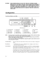
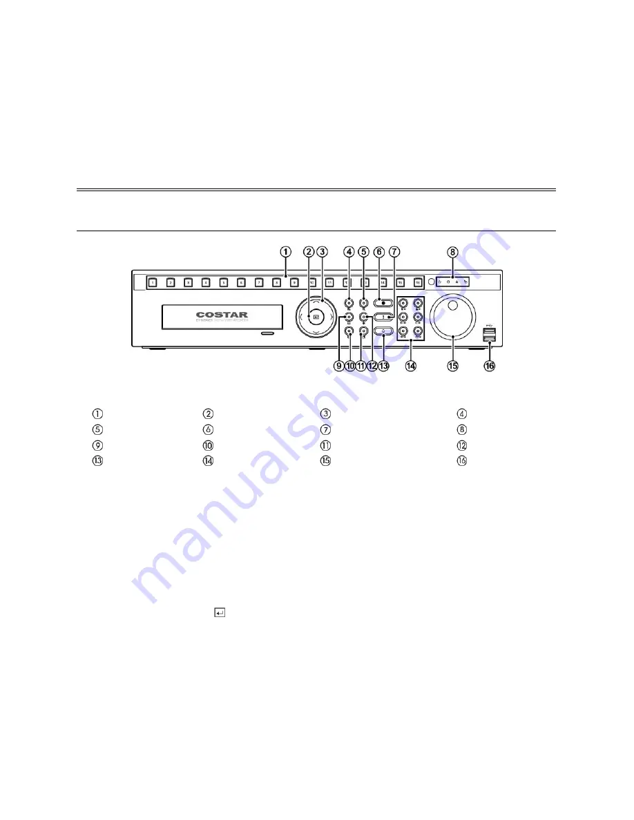
Front Panel Buttons and LEDs


< DVR front panel > 


Camera Buttons 


Enter Button 


Arrow Buttons 


Menu Button 


Zoom Button 


PTZ Button 


Panic Button 


LED 


Display Button 


Monitor Button 


Bookmark Button 


Freeze Button 


Alarm Button 


Playback Buttons 


Jog Dial, Shuttle Ring 


USB Port 


NOTE: 

The infrared sensor on the DVR is just to the right of the arrow buttons.  Make certain that nothing 
blocks the sensor, or the remote control will not function properly. 


When you use wireless communication devices (such as Wi-Fi or Bluetooth) near the DVR, the 
remote control might not function properly. 


You can also use a USB mouse (not supplied) to navigate through the screens and menus much 
like you would on a computer. 


Camera Buttons


Pressing the individual camera buttons will cause the selected camera to display full 
screen. 

Enter Button 


The 

 (Enter) button selects a highlighted item or completes an entry that you 

have made during system setup.


Arrow Buttons


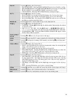
These buttons are used to navigate through menus and GUI.  You can also use them to 
change numbers by highlighting a number in the menu and using the 

Up

 and 

Down 

arrow buttons to increase or decrease the number’s value. 

These buttons are also used to control Pan and Tilt when in the PTZ mode.  When in 
the PIP display format, pressing the 

Up 

and 

Down 

arrow buttons moves the position 

of the small screen counter-clockwise and clockwise.  Pressing the 

Left 

and 

Right 

buttons moves through screen pages in the Live Monitoring mode and Search mode. 

Summary of Contents for CR1615ET

Page 1: ......

Page 2: ......

Page 3: ...he Open Source Guide on the software CD OpenSourceGuide OpenSourceGuide pdf Warning WARNING RISK OF ELECTRIC SHOCK DO NOT OPEN WARNING TO REDUCE THE RISK OF ELECTRIC SHOCK DO NOT REMOVE COVER OR BACK NO USER SERVICEABLE PARTS INSIDE REFER SERVICING TO QUALIFIED SERVICE PERSONNEL The lightning flash with arrowhead symbol within an equilateral triangle is intended to alert the user to the presence o...

Page 4: ...erning UPS consult your UPS retailer This equipment should be remain readily operable 8 Power Cords Operator or installer must remove power and TNT connections before handling the equipment 9 Lightning For added protection for this equipment during a lightning storm or when it is left unattended and unused for long periods of time unplug it from the wall outlet and disconnect the antenna or cable ...

Page 5: ...mmended ambient temperature Tmra for the equipment must be specified so that the customer and installer may determine a suitable maximum operating environment for the equipment Disposal WEEE Waste Electrical Electronic Equipment Correct Disposal of This Product Applicable in the European Union and other European countries with separate collection systems This marking shown on the product or its li...

Page 6: ...terface ATM Interface Connectors Video Input Composite 8 or 16 BNC Monitor Output HDMI 1 HDMI VGA 1 VGA SPOT Composite 1 BNC Audio In 4 RCA connector Audio Out 1 RCA connector Alarm Input Output Terminal Blocks Ethernet Port RJ 45 eSATA Port eSATA RS232 Serial Port Two connector terminal block RS485 Serial Port Two connector terminal block IR Port 1 Remote Control USB Port 2 USB 2 0 Storage Primar...

Page 7: ...Video Out 9 Network Port 9 Audio In Out 9 Power Cord Connector 9 Configuration 10 Front Panel Buttons and LEDs 10 IR Remote Control 12 Turning on the Power 12 Shutting down the System 13 Initial Unit Setup 13 Setup Wizard 14 Operation 17 Live Monitoring 17 Searching Video 18 Remote Program 20 WebGuard 20 StarNET 21 StarNET Mobile 21 ...

Page 8: ...6 ...

Page 9: ...ove 2 4V and for NO Normally Open is below 0 3V and should be stable at least 0 5 seconds to be detected The voltage range of alarm input is from 0V to 5V GND Ground Connect the ground side of the Alarm input and or alarm output to the GND connector NOTE All the connectors marked GND are common NC NO Relay Alarm Outputs The DVR can activate external devices such as buzzers or lights Connect the de...

Page 10: ...e DVR must be powered down to connect or disconnect eSATA devices Power up eSATA devices so they are ready for operation before powering up the DVR Power down eSATA devices after powering down the DVR and then disconnect eSATA devices Factory Reset Switch The DVR can be controlled remotely by an external device or control system such as a control keyboard using RS485 half duplex serial communicati...

Page 11: ...e or wire intended for outdoor use Audio In Out NOTE It is the user s responsibility to determine if local laws and regulations permit recording audio The DVR does not have amplified audio output so you will need a speaker with an amplifier The DVR does not have a pre amplifier for audio input so the audio input should be from an amplified source not directly from a microphone Power Cord Connector...

Page 12: ...y When you use wireless communication devices such as Wi Fi or Bluetooth near the DVR the remote control might not function properly You can also use a USB mouse not supplied to navigate through the screens and menus much like you would on a computer Camera Buttons Pressing the individual camera buttons will cause the selected camera to display full screen Enter Button The Enter button selects a h...

Page 13: ...n between Main and Spot Bookmark Button When in the playback mode pressing the BOOKMARK button adds the current playback point to the bookmark list or moves to the registered bookmark point Freeze Button Pressing the FREEZE button freezes the current live screen Alarm Button The ALARM button has two functions First it will reset the DVR s outputs including the internal buzzer during an alarm Secon...

Page 14: ...ition and the video pauses IR Remote Control ID Button Alarm Button Monitor Buttons Freeze Button Display Button Clip Copy Button Sequence Button Bookmark Button Camera Buttons Zoom In Out Button Triplex Button Preset Set View Button Audio Buttons PTZ Mode Button Focus Near Far Button Arrow Buttons Menu Button Zoom Mode Button Enter Button Play Button Panic Button Pause Button Stop Button Next But...

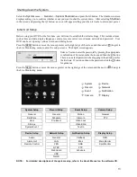
Page 15: ...p screens The Login screen appears Press the MENU button or move the mouse pointer on the right edge of the screen and then select Setup in the Live Monitoring menu System Device Record Network Event Notification Camera Display System Setup Record Setup Event Setup Camera Setup General General Motion General Date Time Schedule Alarm In PTZ User Pre Event Video Loss Storage Video Blind System Event...

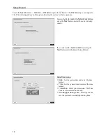
Page 16: ... and select the Next button to start the selected setup wizard If you selected the Quick wizard selecting the Next button starts the Quick Setup Wizard Date Time Setup Date Set the system date and select the date format Time Set the system time and select the time format Time Zone Select your time zone The Time Zone can be selected on the map Use Daylight Saving Time Selecting the box sets the sys...

Page 17: ...elect the desired video quality profile from Higher Video Quality Priority Profile Standard Recording Profile Longer Recording Time Priority Profile Select the Finish button to finish the Quick Setup Wizard and select the Go to Network Setup button to start the Network Setup If you selected the Go to Network Setup select the Next button to start the Network Setup Wizard ...

Page 18: ...Use FEN Highlight and press the button to toggle between On and Off FEN is the technology that automatically sets up your DVR to work seamlessly for remote viewing via your network internet connection For FEN to work naming your DVR will be required FEN Name Enter the DVR name to beregistered on the FEN server The FEN Name you entered should be checked by selecting Test otherwise the FEN changes w...

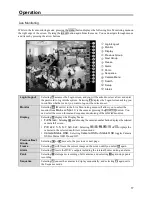
Page 19: ...itor from Main and Spot It is the same as pressing the MONITOR button You can select the screen format and sequence monitoring of the selected monitor Display Selecting displays the Display Menu Full Screen Selecting and choosing the camera number button displays the selected camera full screen PIP 2x2 1 5 1 7 3x3 4x4 Selecting or displays the cameras in the selected multiview screen mode Camera S...

Page 20: ...ng Edit Group enters to the Active Cameo mode Triplex Selecting Search Triplex enters the Triplex mode It enables monitoring recording and playing back at the same time Search Selecting displays the Search Menu All Channels Selecting All Channels exits the live monitoring mode and enters the search mode Triplex Selecting Triplex enters the Triplex mode Setup Selecting enters the Main Setup screen ...

Page 21: ...next page Alarm Selecting resets the DVR s outputs including the internal buzzer during an alarm Panic Selecting starts panic recording of all cameras and selecting again stops panic recording Camera Menu Selecting displays the Camera Menu Zoom Selecting Zoom and choosing the camera number zooms the current playback image of the selected camera on the screen Audio Selecting Audio toggles audio pla...

Page 22: ...r http www dvronline net Entering the DVR IP address or the FEN name will be required when logging in Select between the WEBWATCH Web monitoring and WEBSEARCH Web search modes Entering ID and PASSWORD and clicking the LOGIN button logs in using the selected mode You will need to enter the DVR IP address in the DVR ADDRESS field when running the WebGuard program by entering http www dvronline net S...

Page 23: ...lling the StarNET software run the StarNET program as follows Go to the Start menu on the PC Click StarNET Enter login information NOTE For detailed instructions on operating the StarNET program refer to the User s Manual on the software CD StarNET Mobile StarNET Mobile allows you to access remote sites and monitor live video using mobile devices anytime from virtually anywhere CAUTION This progra...

Page 24: ...efault value is recommended for the Port setting Accounts Enter the User ID and Password used to login to the device iOS based mobile devices 1 Open App Store on your device 2 In App Store enter StarNET Mobile I in the search field 3 Install StarNET Mobile I and open it NOTE To remove the StarNET Mobile I program press and hold the program icon for 2 seconds and then press the button 4 Press the N...

Page 25: ......

Reviews: