
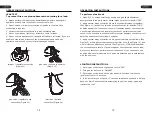

EE
AA
C
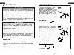
Figure 6
5. Insert three wide glasses (C) into the "L"
clips which have been welded together with
table top, then attach them with bolts (AA)
using the Phillips screwdriver (EE)
(See Figure 6).
Note:
DO NOT tighten the bolts completely.
Note:
After the assembly is completed, the
warning icon and font in the upper right
corner of the glass should face outwards.
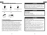
Hardware Used
Bolts (M6 X 5) x 8
AA
Phillips screwdriver x 1
EE
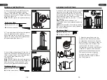
Figure 5
4. Cover and clamp the four narrow glasses
(D) with glass fixture (B) carefully.
Afterwards, tighten the bolts (AA), but not
tighten too much to avoid the glass pieces
being damaged (See Figure 5).
B
D
Figure 4
Hardware Used
Bolts (M6 X 5) x 8
3. Insert the four narrow glasses (D) into
the "L" clips which have been welded
together with table top, then attach them
with bolts (AA) using the Phillips screwdriver
(EE) (See Figure 4).
Note:
DO NOT tighten the bolts completely.
D
E
EE
AA
AA
Phillips screwdriver x 1
EE
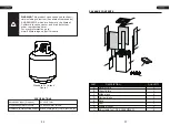
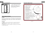
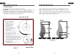
7. Place the gas cylinder into the
cylinder holder. Secure the cylinder
by tightening clockwise the retention
point found on the cylinder holder, so
that the cylinder cannot move from
side to side or fall down. Connect
the regulator, screw the black handle
clockwise to tighten, turn the black
handle counterclockwise to remove.
The knob on the control panel is
turned all the way to the “OFF”
position when the heater is NOT in
use (See Figure 8).
Figure 8
retention point
regulator
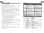
E
E
F
Figure 7
6. With the help of another person, cover and
clamp the three wide glass (C) with metal
shield (A) carefully and tenderly, insert the
fourth wide glass (C) into the "L" clips in the
metal shield (A) firstly, then insert the
bottom of wide glass (C) into the "L" clips in
the table top.
Note:
tighten all the bolts but not
overtighten to avoid the glass pieces being
damaged.
Note:
after assembly, the warning icon and
font on the glass faces out and is located in
the top right corner.
EE
C
Hardware Used
Bolts (M6 X 5) x 8
AA
A
Phillips screwdriver x 1
EE
AA
ASSEMBLY INSTRUCTIONS
ASSEMBLY INSTRUCTIONS
14
15


