background image

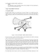
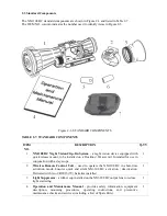
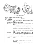
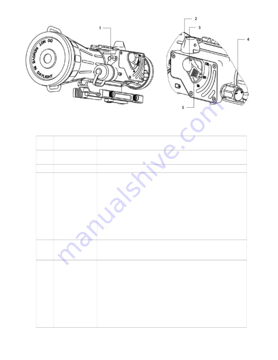
Figure 3-8. NM-108 BC CONTROLS

TABLE 3-1. NM-108 BC CONTROLS AND INDICATORS

ITEM 

NO.

CONTROL / 

INDICATOR

FUNCTION

1

Pivoted Shutter

Closes / opens the photoreceiver when placed in the highest / lowest 
position.

2

Gain Control Knob Adjusts the brightness of the image.

3

Turn Switch

Switches   on   the   NM-108   BC,   when   turned   CW   from   OFF   to   ON 
position.

NOTE:

Both ON and STB positions can only be entered if the switch is 
unlocked by pushing the spring-loaded stop (5) before turning.

Switches the device to standby mode, when turned CCW from OFF to 
STB (see note above).

Switches off the NM-108 BC, when turned CCW/ CW from ON/ STB 
to OFF.

4

Focus Knob

Focuses the objective lens. Adjusts for sharpest view of the scene. The 
total focus range is covered with 1.5 turn of the knob. Directions of 
focus (sharper to softer) are designated by a double arrow on the knob.

5

Spring-loaded Stop

- Remote Control 
  Button

-  Built-in LED
    Indicator

Locks the turn switch in OFF position.

Activates/   deactivates   the   NM-108   BC   in   standby   when   pressed   / 
released.

PERMANENT RED GLOW in viewing area indicates excessive light 
conditions. After 10 seconds the image intensifier tube will be cut off. 
The   NM-108   BC   turns   back   again   when   moved   away   from   the 
excessive light.
FLASHING RED LIGHT in viewing area indicates a low battery. LED 
flashes three times every 3 minutes.

Summary of Contents for NM-108 BC

Page 1: ...NIGHT VISION MODULE COT NM 108 BC Modern Optical Technologies...

Page 2: ...nt clean Protect it from moisture dramatic temperature changes and electric shocks DO NOT drop or hit the equipment Protect the equipment from overexposure to light DO NOT activate the equipment in da...

Page 3: ...Manual COT NM 108 BC will be referred to as the NM 108 BC the device or the equipment Reference data for the estimation of ambient illumination levels can be found in Appendix A Chapter 1 INTRODUCTIO...

Page 4: ...on the photocathode of the image intensifier tube IIT The light energy causes electrons to be released from the cathode After being amplified the electron flow represents an intensified version of the...

Page 5: ...powered by a single AA or CR123A battery The NM 108 BC uses a LED indicator to show the operator when the bright light protection system is activated or to indicate a low battery The Picatinny Weaver...

Page 6: ...2 Specifications TABLE 2 2 SYSTEM DATA ITEM DATA Magnification Unity 1X Boresight Characteristics Accuracy Retention Repeatability Factory aligned to 0 75 MOA or better Permanent to within 1 5 MOA or...

Page 7: ...unction can be completely disabled TABLE 2 5 OPTICAL DATA ITEM DATA Objective Lens Focal Length 108 mm Objective Lens F number 1 1 5 Focus Range 10 m to infinity Field of View 9o Exit Pupil Diameter 4...

Page 8: ...a Picatinny Weaver rail Intended for use in conjunction with a day scope 1 2 Wireless Remote Control Unit used to operate the NM 108 BC in short time activation mode Ensures quick and silent NM 108 BC...

Page 9: ...oonlight starlight etc to operate Factors that can reduce natural night light and negatively affect the efficiency and operation of the NM 108 BC in clude rain fog sleet snow and smoke passing cloud c...

Page 10: ...R IN THE BATTERY CAP 3 1 2 Installing the NM 108 BC on a Picatinny Weaver Rail WARNING When installing the equipment on a weapon be sure the weapon is clear and the safety is on be fore proceeding WAR...

Page 11: ...om the storage case Put it on the output lens in place of the cap 3 Unlock the clamping device of the NM 108 BC mount by pushing down on the dogs A see Fig ure 3 4 and unlocking the levers B 4 Install...

Page 12: ...n on the cam B and turn the nut A CW CCW respectively in one two increments see note below Much like when the cam B is released back ward moving springs will cause the nut A to slide back into its hol...

Page 13: ...s remote C Install adapter on the rail Insert the wireless remote control unit in the adapter Figure 3 7 REMOTE CONTROL UNIT 3 2 Controls and Indicators CAUTION DO NOT force the equipment controls pas...

Page 14: ...s off the NM 108 BC when turned CCW CW from ON STB to OFF 4 Focus Knob Focuses the objective lens Adjusts for sharpest view of the scene The total focus range is covered with 1 5 turn of the knob Dire...

Page 15: ...n the device on After a slight delay a green glow will appear in the day scope s output lens CAUTION AVOID EXPOSING THE DEVICE TO BRIGHT LIGHT SOURCES SUCH AS FIRELIGHT HEADLIGHTS SEARCHLIGHTS ETC AS...

Page 16: ...ccessories are clean and dry before placing them into the storage case 8 Place the NM 108 BC and any accessories into the storage case 9 Store the NM 108 BCand accessories in the appropriate locations...

Page 17: ...r missing 6 Switch Check for operation without battery Switch is inoperative 7 Lenses Inspect for cleanliness scratches chips or cracks Clean as required Chipped or cracked Scratches hinder vi sion th...

Page 18: ...17 Viewed Image Inspect for any operational defects refer to Sec tion 4 3 Inspection Criteria for Proper Image In tensifier Tube Operation Shading edge glow flashing flickering and intermittent opera...

Page 19: ...ead Damaged cap thread Clean the thread Please contact Customer Support Battery adapter difficult to re move Check for damaged adapter and battery cap If damaged please contact Cus tomer Support Light...

Page 20: ...a loose bat tery adapter or a weak battery If flickering continues please contact Customer Support 4 3 2 Cosmetic Blemishes Cosmetic blemishes are usually the result of manufacturing imperfections Th...

Page 21: ...return the NM 108 BC Verify that emission points are not simply light sources present in the scene you are observ ing Emission points are acceptable if they do not interfere with the user s ability t...

Page 22: ...rument and must be handled carefully at all times to prevent damage 4 4 2 Cleaning Procedures CAUTION Thoroughly dry each item before placing them into the storage case Clean the NM 108 BC as follows...

Page 23: ...th the minus contacts directed towards the electric board as the minus sign etched on the board indicates 3 Replace the cover and retighten the screws A Figure 4 6 REMOTE CONTROL UNIT BATTERY INSTALLA...

Reviews: