18
ENG
LI
SH
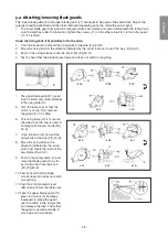
6.2 Attaching and adjusting the rip fence
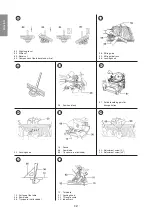
1. Attach the rip fence guide holder (45) in the slot (46) in the table.
2. Set it to the desired width according to the scale and lock the
knob (48).
3. Undo the locking knob (47).
4. Slide the fence (49) into the holder (45) so that it stops just where
the saw blade (36) emerges from the table (see the index line
50). Note: This is important to prevent the workpiece from being
ejected back towards the operator if it gets squashed between the
rip fence and saw blade. Note: The setting should be changed
depending on the thickness and angle setting.
5. Lock the knob (47) so that the fence is fastened in place.
Note:
The rip fence guide can be mounted in the holder (45) in four different
ways.
The rip fence must be parallel to the saw blade, check it as follows:
1. Set the saw blade to its maximum height above the table.
2. Mark one of the teeth.
3. Rotate the blade by hand until the marked tooth is level with the
table, measure the distance from the tooth to the rip fence. Use
a try square, set square, etc.
4. Rotate the blade backwards by hand until the marked tooth is
level with the table, measure the distance from the tooth to the rip
fence at that place. If the two distances (A) and (B) are the same,
the rip fence is parallel to the saw blade.
5. Adjust the rip fence guide if necessary: the holder (45) has an
adjustment screw on the outside, undo the locking knob (48)
slightly, turn the adjustment screw until the rip fence is parallel
to the saw blade. Tighten the locking knob (48).
6. Make sure that the saw blade can rotate freely and that all safety
guards work properly.
Note:
Do not lift the rip fence, the holder can break.
6.3 Mitre guide
1. Attach the fence (57) to the mitre guide (58).
2. Fit the mitre guide (58) to the table by sliding the long aluminium
section of the mitre guide into the track (59) at the front of the
table.
Summary of Contents for 2502W
Page 107: ......

