25
ENG
LI
SH
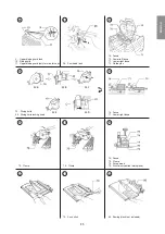
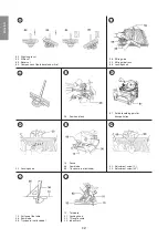
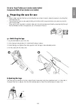
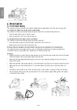
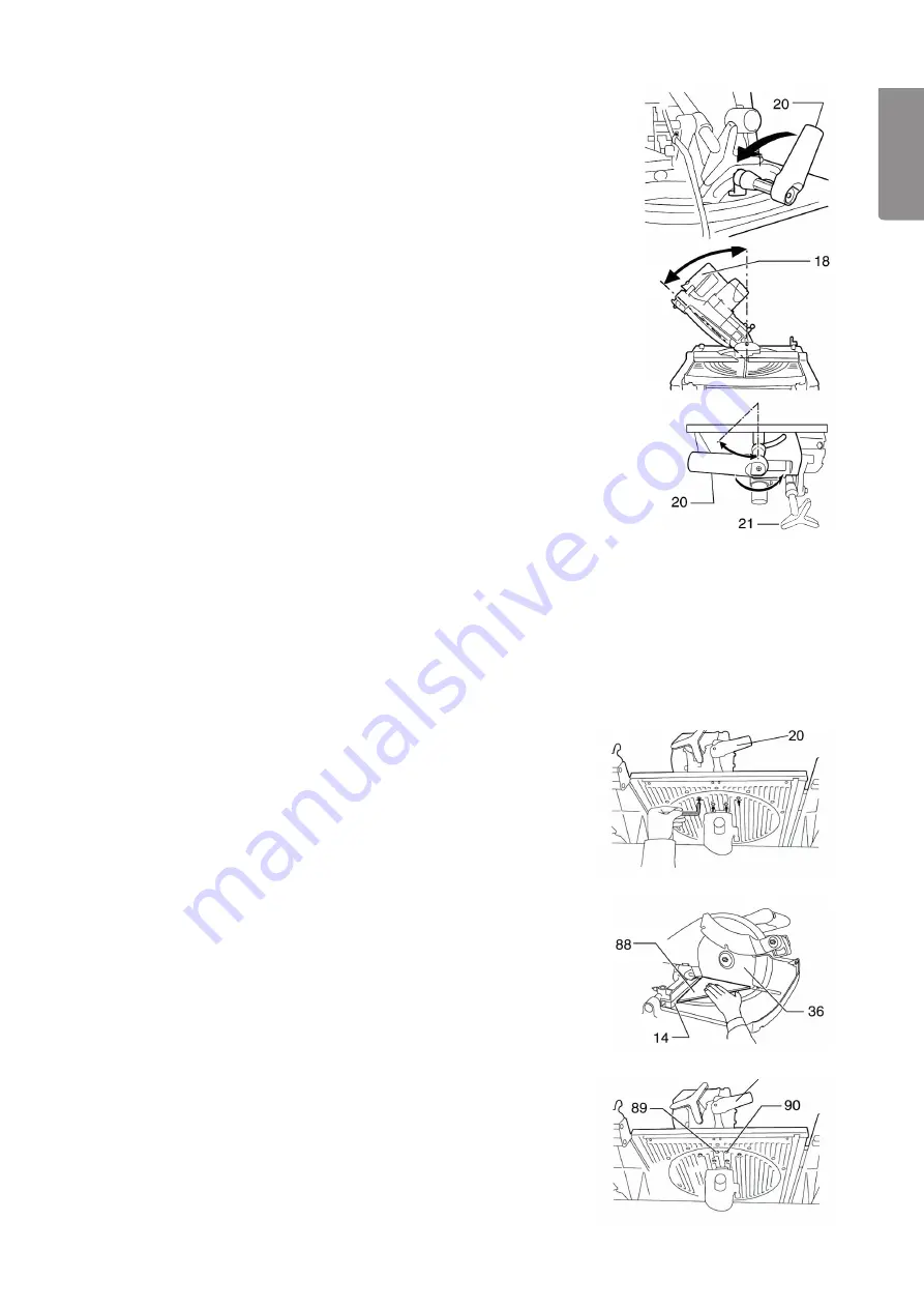
9.3 Setting the tilt of the blade (bevel cutting)
Remember to check that the blade can rotate freely after every adjustment.
The angle between the saw blade and the fence must be exactly 90°.
Compound Mitre Saw
1. Turn the locking knob (20) anticlockwise, turn the saw head to the right
until the desired angle is shown on the scale.
2. Tighten the locking knob (20) to lock the saw head at the desired angle.
Note:
Make sure that the handle (18) is at maximum elevation before the
blade is tilted. Remember to tighten the locking knob (20) after changing the
blade tilt angle.
Circular Saw
1. Turn the locking knob (20) anticlockwise, turn the saw head to the left
until the desired angle is shown on the scale.
2. Tighten the locking knob (20) to lock the saw head at the desired angle.
9.4 Adjusting the cutting depth
Adjust the cutting depth of the saw when the saw is in circular saw mode
(motor under table). Turn the adjustment knob (21) anticlockwise to raise
the saw blade and clockwise to lower it.
Warning:
Adjust the blade so that it does not protrude too long through
the table when cutting thin material, it should just be slightly higher than
the thickness of the material.
Note:
The lock (28) cannot be altered when the saw head is under the table.
9.5 Adjusting the cutting angle settings
The combination saw is carefully calibrated at the factory, but the settings
need to be checked from time to time. (The saw should be in compound
mitre saw mode)
Adjusting the mitre angle:
1. The four adjusting screws are located underneath the table, undo them.
2. Lower the saw head as far as possible and lock it using the saw head
lock (28).
3. Place a try square on the table, hold it against the fence and saw blade.
4. Turn the table until “0” lines up with the index arrow on the table.
5. Tighten the screws.
Adjusting the tilt angle 0°:
1. Lower the saw head as far as possible and lock it using the saw head
lock (28).
2. Undo the locking lever (20) on the back.
3. Unscrew the adjustment bolt (89) 2 – 3 turns anticlockwise.
4. Screw the adjustment bolt (89) back clockwise to the correct angle.
5. Adjust the position of the index arrow if necessary so that it is set to “0”.
Adjusting the tilt angle 45°:
1. First adjust the tilt angle 0°.
2. Tilt the saw head down to the left as far is it will go.
3. Turn the adjustment bolt (90) until the arrow points to “45”.
20
Summary of Contents for 2502W
Page 107: ......

