8
EN
GL
IS
H
10
18
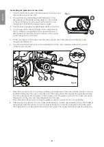
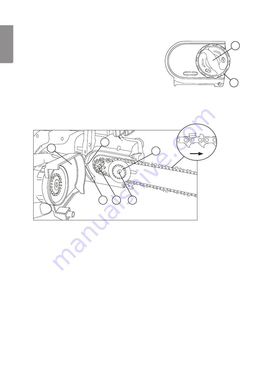
Assembling the guide bar and saw chain:
1. Turn the centre locking knob (18) anticlockwise to loosen it and
remove the sprocket cover (19).
2. The guide bar has a tensioning wheel (16) fixed to it. Turn
the guide bar so that the tensioning wheel is on the outside
of the bar, fit the bar in such a way that the bolt (15) sticks
through the hole in the tensioning wheel (see fig.8).
3. Turn the tensioning wheel (16) anticlockwise as far as it will turn.
4. Turn the saw chain so that the edges of the cutting links on
the top of the bar are pointing forwards toward the nose of
the bar (the saw chain pulls along the bottom of the bar and
pushes along the top of the bar).
5. Fit the saw chain so that it passes over the drive sprocket and in the guide track all the way round
the guide bar. (See fig. 8)
6. Turn the tensioning wheel clockwise and carefully tension the chain, making sure that it sits properly
on the bar and sprocket.
7. Attach the sprocket cover (17) by lining up the peg (C) on the back of the cover with the hole (D) in the saw
and then folding down the cover so that the bolt of the locking knob (18) is against the guide bar bolt (15).
Turn the locking knob (18) clockwise so that it screws on to the guide bar bolt (15). The chain can now be
tensioned by turning the outer, tensioning knob (19) clockwise.
(The centre knob (18) is only for locking the guide bar and the outer knob (19) is for tensioning.)
8. Checking the chain tension: The saw chain should be able to be lifted approximately 5 mm in the middle of
the guide bar when the tension is correct. Adjust as necessary: Undo the locking knob (18) a little, adjust
the chain tension by turning the outer knob (19), then tighten the locking knob (18) to keep the set tension.
Fig. 7
10
19
D
C
17
Fig. 8
10
14
15
16
Summary of Contents for YT4755
Page 83: ...83...


