background image

3-6. AC Safety Grounding

The AC output ground wire should go to the grounding point for your loads

for example, a distribution panel ground bus ).

3-6-1. Neutral Grounding (GFCI'S)

3-6-1-1. 110V models

The neutral conductor of the AC output circuit

               of the Inverter is automatically connected to the safety
               ground during inverter operation. In accordance with the 
               National Electrical Code requirements that separately derived 
               AC sources (such as inverter and generators) have their 
               neutral conductors tied to ground in the same way that the 
               neutral conductor from the utility is tied to ground at the AC 
               breaker panel.    For models configured with a transfer relay, 
               while AC utility power is presenting and the Inverter is in 
               bypass mode, this connection (neutral of the Inverter's AC 
               output to input safety ground) is not present so that the utility 
               neutral is only connected to ground at your breaker panel,
               as required.

3-6-1-2.


230V models

There is no connection made inverter interior 

               between either the line or neutral conductor to the safety ground.

WARNING!

Risk of electronic shock.  Use only Pass and Seymour, type 
2095-W or 7899-W, ground – fault circuit-interrupter 
receptacles.  Others may fail in operating the inverter when 
connecting to the inverter's equipment.

-14-

Summary of Contents for SE350 series

Page 1: ...SE350 Series Pure Sine Wave Inverter User s Manual WWW COTEK COM TW...

Page 2: ...1 Front Panel Operation 3 2 Rear Panel Operation 3 3 Protections Features 3 4 Installation 3 5 Making DC Wiring Connections 3 6 AC Safety Grounding 3 7 Inverter Operation 4 Troubleshooting guide 5 Mai...

Page 3: ...eries or Flammable materials or in locations which require ignition protected equipment This includes any space containing gasoline powered machinery fuel tanks or joints fittings or other connection...

Page 4: ...isolated design High efficiency Capable of driving inductive capacitive loads at the start moment A LED Indicator with twin color displays all operation status Loading and temperature controlled cool...

Page 5: ...ature 20V 0 5V 21V 0 5V 24V 0 5V 30V 0 5V 31V 0 5V 29V 0 5V 40V 1V 42V 1V 48V 1V 60V 1V 62V 1V 58V 1V 10V 0 25V 10 5V 0 25V 12V 0 25V 15V 0 25V 15 5V 0 25V 14 5V 0 25V 20V 0 5V 21V 0 5V 24V 0 5V 30V 0...

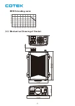
Page 6: ...2 2 M SE350 de rating curve echanical Drawing of Socket 6 150 5 91 68 2 68 35 7 1 41 116 0 4 57 22 0 87 127 5 00 187 7 36 0 20 30 40 35 45 55 50 60 25 200 250 300 350 400...

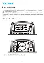
Page 7: ...ced line of mobile AC power systems available To get the most out of the power inverter it must be installed and used properly Please read the instructions in this manual before installation and opera...

Page 8: ...t Voltage Selected by Dip Switch Power Saving Dip Switch ON OFF 1 0 Frequency 50Hz 60Hz Output Voltage S1 S2 Dip Switch 0 1 0 0 0 1 0 1 1 1 C A V 0 0 2 C A V 0 0 1 8 C A V 0 2 2 C A V 0 1 1 C A V 0 3...

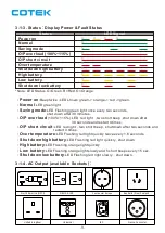
Page 9: ...D shows green orange red green Normal LED green light Saving mode LED Flashing green light once every two seconds shut down after 30 minutes O P over load 100 115 LED red light two short beep shut dow...

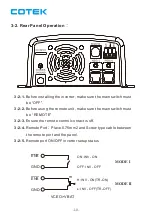
Page 10: ...nit make sure the main switch must be REMOTE 3 2 3 Ensure the remote control contact is off 3 2 4 Remote Port Place 0 75mm2 and Screw type cable between the remote port and the panel 3 2 5 Remote port...

Page 11: ...48V battery or the other power sources is positive is negative Reverse polarity connection will blow internal fuse and may damage inverter permanently Model Minimum Maximum 62 0 15 5 10 0 40 0 20 0 31...

Page 12: ...ing requirements 3 4 1 Dry Do not allow water to drip or splash on the inverter 3 4 2 Cool Ambient air temperature should be between 20 and 40 the cooler the better 3 4 3 Safe Do not install in a batt...

Page 13: ...ut terminals of the Inverter Your cables should be as short as possible Ideally less than 6 feet 1 8 meters enough to handle the required current in accordance with the electrical codes or regulations...

Page 14: ...the neutral conductor from the utility is tied to ground at the AC breaker panel For models configured with a transfer relay while AC utility power is presenting and the Inverter is in bypass mode thi...

Page 15: ...he power inverter is now ready to deliver AC power to your loads If there is several loads use turn them on separately after the inverter has been ON in order to prevent the OVP present caused by the...

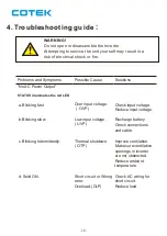
Page 16: ...nates the red LED a Blinking fast Over input voltage OVP Check input voltage Reduce input voltage b Blinking slow Low input voltage UVP Recharge battery Check connections and cable c Blinking Intermit...

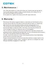
Page 17: ...anty will be considered void if the unit has suffered any obvious physical damage or alteration either internally or externally and does not cover damage arising from improper use such as plugging The...

Page 18: ...No 33 Sec 2 Renhe Rd Daxi Dist Taoyuan City 33548 Taiwan Phone 886 3 3891999 FAX 886 3 3802333 2015 12 A3 E mail sales cotek com tw http www cotek com tw...

Reviews: