COTES C30
OPERATING AND SERVICE HANDBOOK
page 42/48
Connection need for condensation (LK)- and Heat Recovery (HR) unit
– Drain
When installing a HR or LK unit, the unit must be placed in an upright position, with the bottom plate
parallel to the horizontal plane. It is critical that the unit is positioned correctly, otherwise the water
condensate will not be sufficiently drained.
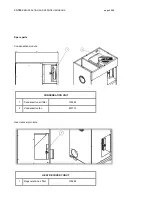
The heat recovery unit HR is equipped with one drain connection that has to be guided to the drain in
the building as minor condensate may get formed inside the unit.
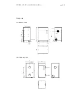
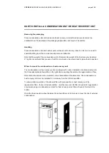
The condensation unit LK is equipped with two drain connections found on the bottom of the unit. The
drain connection to the left (seen from the front) is the main drain.
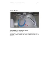
For both the Heat recovery unit, and the LK unit, a hose must be mounted to the drain connections
that guides water to a drain in the building. The hose that is connected to the drain pipe, must be of
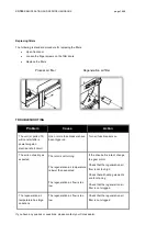
sufficient size and mounted on the outside of the drain pipe (see illustration on the next page).
Minimum internal diameter of the Hose = 14mm
For the LK/HR unit’s main drain, an “air-lock” must be made with, or in connection with, the drain
hose, and must be minimum 30mm below the drain. Fo
r the LK unit, if an ‘air-lock’ is not in place, the
low relative pressure inside the unit will pull outside air in, and stop the water from draining.
The secondary drain does not need an air-lock.
We recommend keeping some free space below the module to make sure it is easy to install drain
hose(s) and an air-lock. An additional floor or wall bracket can be provided to make sure there is
enough space. For details, please contact your Cotes dealer, or Cotes.
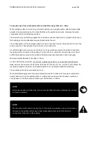
NOTE
Before the machine is started, t
he ‘air-lock’ must be filled with water, otherwise the unit may
not function properly.
NOTE
The two drain must not be connected by a Y connection and guided in one common hose to
the drain in the building. Water has to float independently from each of the LK drain
connections to the drain in the building.

