background image


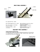
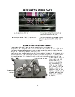
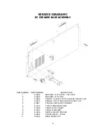
PERF SHAFT & STRIKE PLATE 


A

 – Support Bar – F-0232 


This is the shaft that the roller wheels 


 and perf score are mounted on. 


– Lower Sensor Eye Assy. – S-AAM-0230 

    Located in the platen strike plate, directly 


    below the upper sensor. These two must  


     align. 


REMOVING THE PERF SHAFT 

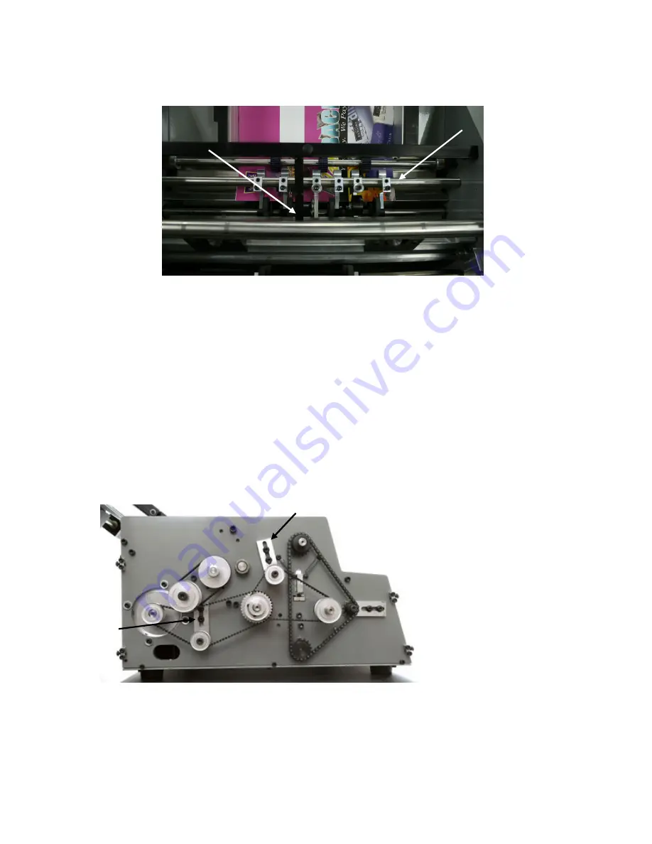
Loosen the operator side cover. Locate and remove the perf shaft lock collar.  
Next, remove the non-operator side cover. Loosen both of the belt tensioner idler pully’s. You do 
not need to remove these as loosening them will allow enough movement to free the pully’s of 
the perf shaft. Slide the perf shaft out the pulley side. 
It is only necessary to slide the shaft out about 6 to 8 inches. With the shaft slid to the side, you 
can access the lower hubs and reconfigure them as needed to complete any job. After you have 
configured the lower shaft, replace the shaft into its bearing and secure the shaft collar. The 

shaft should not be able to 
move side to side. With 
both drive belts in 
Position, re-tension the 
belt idlers and tighten 
while applying constant 
firm pressure on the belts 
by pushing down on the 
tops of the brackets with 
the large T-handle wrench 
supplied. Replace covers. 
Align upper assemblies 
accordingly.  


14 

Loosen both screws 

Loosen both 

screws 

Summary of Contents for EZCREASER

Page 1: ...EZCREASER Serial Number ___________________________ Date ___________________________________ 4 2009 Version 1 6...

Page 2: ...d inside creased edge Counts trademarked RAC System assures a consistent controlled compression that is easily adjustable to the demands of any sensitive media The EZ Creaser with it s microprocessor...

Page 3: ...nent Identification 9 Adjusting Feed Rails 10 Setting the Automatic Feeder 11 Fanning the Paper 11 Loading the Feeder 12 Replacing the Feed Wheels 12 Feeding Notes 12 Replacing the Friction Plate 13 C...

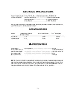
Page 4: ...11X17 Sheet est 5 Sheet est Feet per Sec Perf Mode 2 5 8500 12500 Crease Mode 2 0 2500 4400 SPECIFICATIONS Net Weight EZ CREASER 250 lbs Overall Dimensions 32 Lx27 Wx26 D Boxed Dimensions 36 Lx36 Wx3...

Page 5: ...edures BE ALERT BE CAREFUL CARE AND MAINTENANCE The EZ CREASER is a precision machine It is very important to keep it free of excessive dust dirt and foreign matter We recommend that you keep the mach...

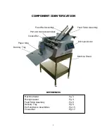
Page 6: ...ssembly Microprocessor Delivery Tray Machine Stand Perf and Score Assemblies Crease Bar Paper Stop Machine Stand Pg 3 Microprocessor Pg 4 Feed Table Assembly Pg 9 Delivery Tray Pg 9 Perf and Score Ass...

Page 7: ...in front so tray hooks under steel dowels directly below the exit shaft shaft Locate the magnetic paper stops and position them on the tray 6 Inspect the remaining parts and place them near the machi...

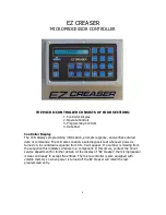
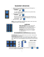
Page 8: ...onducts a self diagnosis test whenever power is turned on A countdown sequence from 9 to 0 will appear If a number is missing from the sequence this indicates a failure in a component If this occurs c...

Page 9: ...d crease designation Enter Yes Stores input information from data keys and answers display prompted questions Clear No Erases errors entered and prompts for clearing total count Answers no to display...

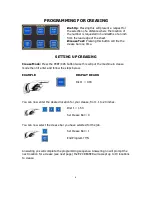
Page 10: ...CRS button twice this will put the machine in crease mode then hit enter and follow the steps below EXAMPLE DISPLAY READS Dist 1 0 00 You can now enter the desired location for your crease from 1 to...

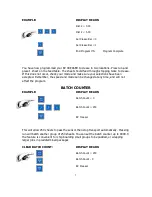
Page 11: ...ave been accepted Remember the speed and mode can be changed at any time and will not affect the program BATCH COUNTER EXAMPLE DISPLAY READS Batch Count 0 Batch Count 250 EZ Creaser This will allow 25...

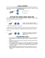
Page 12: ...indicating that the sheet detector is activated To turn off 1 Dashed line on display will vanish from display thus indicating that the sheet detector is off PROGRAMMING NOTES The micro controller is c...

Page 13: ...t Feed Rail Lock Down H 0825 Releases and tightens feed rails to knob assembly adjust for different size jobs DELIVERY TRAY ASSEMBLY INSTALLING THE DELIVERY TRAY The delivery tray is made to fit 2 dif...

Page 14: ...rf by folding over and aligning the perfed edge Perf holes should line up within a blade s width If they do not line up adjust rails accordingly moving your left rail first and then adjusting the righ...

Page 15: ...d the auto feed wheel must move fig freely and should not be gripped FANNING THE PAPER To prepare a stack of paper or sets for feeding it must be fanned This will loosen the stack as well as form a we...

Page 16: ...ing to run even the simplest job The adjustments previously discussed are very important The EZ CREASER is capable of running 20lb single sheets 4 part forms and 100 lb cover It is also very capable o...

Page 17: ...in simply reverse the procedure of removing CHECKING THE SENSORS 1 Turn machine power on and allow startup count down mode to complete 2 At this time your display on your control board should read EZ...

Page 18: ...ee the pully s of the perf shaft Slide the perf shaft out the pulley side It is only necessary to slide the shaft out about 6 to 8 inches With the shaft slid to the side you can access the lower hubs...

Page 19: ...32x1 2 button head socket H 0250 Screw 10 32x 1 1 2 socket cap H 0270 Screw 1 4 20x1 4 socket set H 0275 Screw 1 4 20x1 4 socket set H 0278 Screw 1 4 20x1 4 socket half dog H 0456 Washer flat 20 H 05...

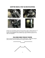
Page 20: ...side of the finished fold Scores may be made on the EZ CREASER in three different ways using the different grooves on the lower score assembly FOLDING DIRECTION OF PAPER There is a correct and incorre...

Page 21: ...aft C Upper crease die D Pressure Adjust bearing blocks RAC Rollers E Lower crease die F Drive chain tensioner SEE DRIVE CHAIN TENSIONER ON PAGE 13 G Return springs SEE SERVICE DIAGRAM A ON PAGE 21 H...

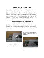
Page 22: ...ar pressure as counterclockwise will decrease the pressure Once the adjustment to the bar has been made slightly tighten the thumb lock and re set the block set screws ADJUSTING RAC TOP DEAD CENTER Th...

Page 23: ...he Lower crease die can easily be changed to accommodate thicker stocks by removing the non operator side cover slide the bar out and flip it over to use the wider die channel Please note custom die s...

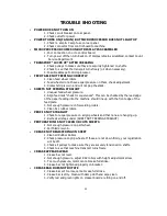
Page 24: ...checked by the lead edge of the paper feeding into the machine should line up with the front edge of the feed plate 3 Not enough pressure on forwarding rollers 4 Clean ALL rubber rollers PERF IS NOT...

Page 25: ...SERVICE DIAGRAM A EZ CREASER SIDE FRAME LEFT NON OPERATOR Paper folding direction 21...

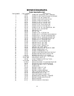
Page 26: ...LDER SLOT 21 H 1669 WASHER 3 8 ID X 125 THICK 22 H 1670 WASHER 3 8 ID X 095 THICK 23 H 0320 SCREW 1 4 20X1 SOCKET CAP 24 H 0480 WASHER FLAT BURR WHEEL 25 H 0669 BEARING ROLLER 375ID X 875OD X 280W 26...

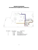
Page 27: ...EZ CREASER SIDE FRAME RIGHT OPERATOR ITEM NUMBER PART NUMBER DESCRIPTION 1 S CRZ 0018 SWITCH ASSY 2 E 1240 CREASER BOARD 3 H 0635 COLLAR SHAFT 1 2 4 F 0808 SIDE COVER MOUNT BLOCK APP 5 F 2646 CREASER...

Page 28: ...0465 WASHER 1 4 NYLON 3 H 0285 SCREW 1 4 20X1 2 BUTTON HEAD SOCKET CAP 4 H 0375 SCREW 1 4X1 4 SHOULDER SOCKET CAP 5 E 0851 FUSEHOLDER QUICK CONNECT 6 E 0705 CIRCUIT BREAKER 3 AMP 7 E 0795 FUSE 313 25...

Reviews: