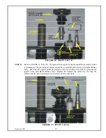
STEP 6
Continue to assemble lengths of pipe and elbows necessary to reach from the ceiling support box
up through the roof line. Galvanized pipe and elbows may be utilized in the attic, as well as
above the roof line. The galvanized finish is desirable above the roof line, due to its higher
corrosion resistance.
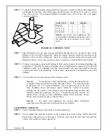
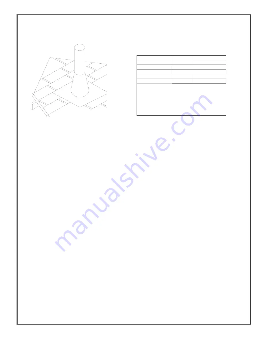
FIGURE 20: CHIMNEY VENT
STEP 7
Slip the flashing over the pipe sections protruding through the roof. Secure the base of the
flashing to the roof with roofing nails. Insure the roofing material overlaps the top edge of the
flashing to the roof with roofing nails. Insure the roofing material overlaps the top edge of the
flashing as shown. Verify that you have at least 1" clearance to combustibles at the roof line.
STEP 8
Continue to add pipe sections until the height of the vent cap meets the minimum building code
requirements. Note that for steep roof pitches, the vent height must be increased. In high wind
conditions, nearby trees, adjoining roof lines, steep pitched roofs, and other similar factors can
result in poor draft, or down-drafting. In these cases, increasing the vent height may solve this
problem.
STEP 9
Twist lock the vent cap onto the top of the chimney system.
Note (1):
For multi-story vertical installations, a ceiling fire stop (Part 963)
is required at the second floor, and any subsequent floors. The opening should
be framed to 10" x 10" inside dimensions. Any occupied areas above the first
floor, including closets and storage spaces, which the vertical vent passes
through, must be enclosed. The enclosure may be framed and sheet-rocked with
standard construction materials, leaving a 1" minimum clearance between the
outside of the vent pipe, and the combustible surfaces of the enclosure. Do not
fill any of the required air spaces with insulation.
Note (2):
For direct vent appliances, the vent/air intake termination
clearances above the high side of an angled roof are as follows:
CATHEDRAL CEILINGS
STEP 1
Follow installation Steps 1 and 2 under Vertical Terminations.
STEP 2
Using a plumb bob mark the centerline of the venting system on the ceiling. Drill a small hole
through the ceiling and roof at this point. From the roof, locate the drill hole and mark the
outline of the cathedral ceiling support box.
Version 1.0h
31
ROOF PITCH
FEET
METERS
Flat to 6/12
1
0.3
7/12 to 9/12
2
0.6
10/12 to 12/12
3
1.2
13/12 to 16/12
6
1.8
17/12 to 21/12
8
2.4
NOTE:
For direct vent appliances, the
vent/air intake termination clearances above
the high side of an angled roof are listed
above.
Summary of Contents for Bayvue DV 30
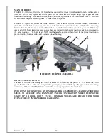
Page 48: ...SAFETY LABEL Version 1 0h 47...

