background image


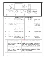
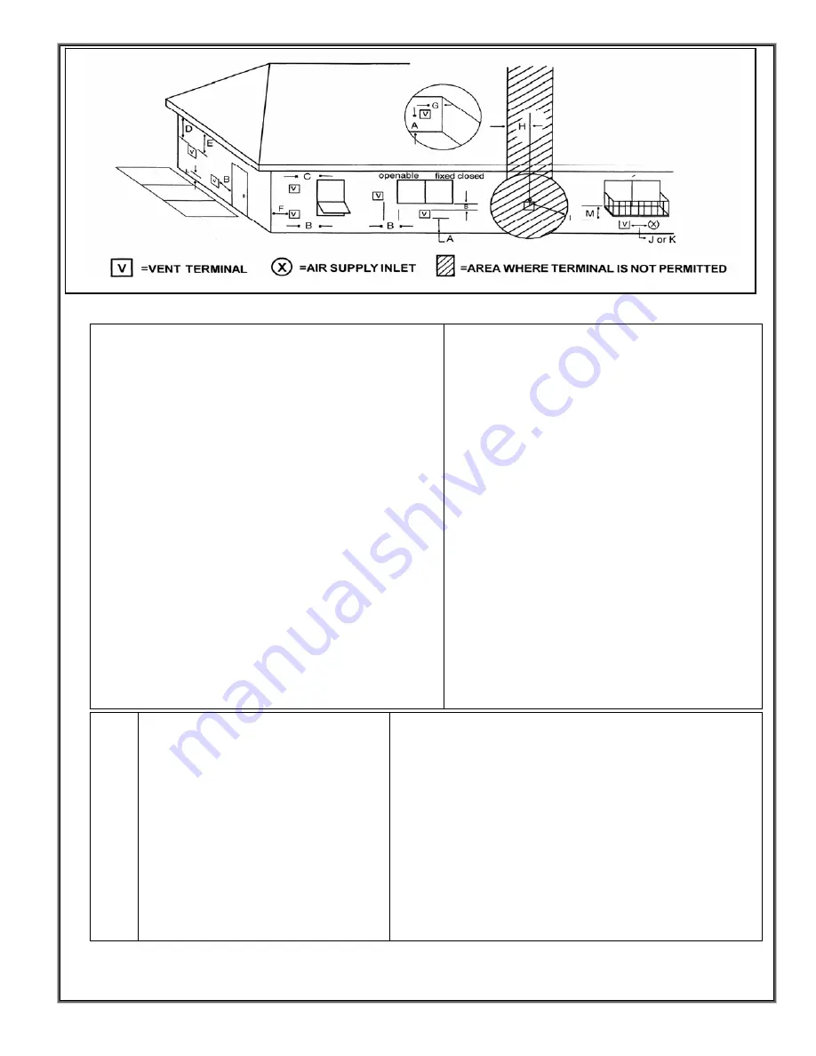
FIGURE 3:  CLEARANCE REQUIREMENTS 

= 12 in. 

Clearances above grade, 
veranda, porch, deck or balcony 
 

= 3ft. (U.S.A) 
= 6ft (Canada) 

 
Clearance to service 
regulator vent outlet 


= 12 in. 
 
 
=  9 in. (U.S.A) 
   12 in(Canada) 

Clearances to window or door 
that may be opened 
 
Clearance to permanently closed 
window 

 = 9 in.(U.S.A) 
= 12 in. (Canada) 

 
Clearance to non 
mechanical air supply 
inlet to building or the 
combustion air inlet to 
any other appliance 

D* 

= 18 in. 
    

Vertical clearance to ventilated 
soffit located above the terminal 
within a horizontal distance of 2 
feet (60 cm) from the center-line 
of the terminal 


= 3ft. (U.S.A) 
= 6ft (Canada) 


Clearance to a mechanical 
air supply inlet 

E* 


= 18 in. 
 
= 9 in. 
 
=  6 in. 

Clearance to unventilated soffit 
 
Clearance to outside corner 
 
Clearance to inside corner 
 

**L 

 = 7 ft. 

Clearance above paved 
sidewalk or a paved 
driveway located on 
public property 

= 3 ft. (Canada) 

Not to be installed above a gas 
meter/regulator assembly within 
3 feet (90cm) horizontally from 
the center-line of the regulator 

***M 

= 18 in. 

Clearance under 
veranda, porch, deck 
or balcony 


** 


*** 

30 in. minimum for vinyl clad soffits 


A vent shall not terminate directly above a 
sidewalk or paved driveway that is located 
between two single family dwellings and 
serves both dwellings. 
 
Only permitted if veranda, porch, deck or 
balcony is fully open on a minimum of 2 
sides beneath the floor. 
 
NOTE: Local codes or regulations may 
require different clearances. 

WARNING:

 In the U.S.A.:

 Vent system termination is 

NOT

 permitted in screened porches.  Follow all sidewall, 

overhang and ground clearances as stated in the instructions. 
 

In Canada:

 Vent system termination is 

NOT

 permitted in 

screened porches. Vent system termination is permitted in a 
porch area with two or more sides open. Follow all 
sidewalls, overhang and ground clearances as stated in the 
instructions. 
 
Country Flame Technologies assumes no responsibility for 
the improper performance of the fireplace when the venting 
system does not meet requirements.  

TABLE 3:  CLEARANCE DEFINITIONS 

Version 1.0h 


Summary of Contents for Bayvue DV 30

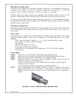
Page 1: ...his manual are not followed exactly a fire or explosion may result causing property damage personal injury or loss of life IF YOU SMELL GAS FOR YOUR SAFETY Do not light any appliance Do not touch elec...

Page 2: ...TS 14 NG CONVERSION KIT BV 3003 CONTENTS 14 PROPANE CONVERSION KIT 15 NATURAL GAS CONVERSION KIT 15 PROPANE CONVERSION 15 INTAKE AND EXHAUST CONDITIONS 18 SEALED VENTING SYSTEM 18 THERMOSTAT FAN CIRCU...

Page 3: ...ON 36 GENERAL CLEANING 36 GENERAL SAFETY 36 GENERAL PERIODIC INSPECTIONS 36 CLEANING A PAINTED SURFACE 36 CLEANING PLATED SURFACES 37 DOOR INSTALLATION 37 DOOR SEAL 37 MAIN ORIFICES 38 GAS FLAME INSPE...

Page 4: ...o hearing from you as this product becomes part of your home heating solution This manual is written to provide information that will assure proper installation proper maintenance and correct operatio...

Page 5: ...d firing of the gas appliance At a minimum annually clean and repaint the interior surfaces to prevent deterioration More frequent cleaning may be required due to carpet lint bedding material dust etc...

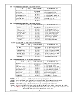
Page 6: ...MINIMUM CLEARANCES AND VENT AIR INTAKE PIPE CLEARANCES TABLE 1 BAYVUE DV SPECIFICATIONS BAYVUE DV 46 BAYVUE DV 30 NATURAL GAS PROPANE NATURAL GAS PROPANE Altitude 0 4500 0 4500 0 4500 0 4500 Manifold...

Page 7: ...pproval by the local authority having jurisdiction GAS SUPPLY CONNECTION Version 1 0h 6 A gas supply line must be installed by a qualified professional and must conform to National Standards NFPA 54 n...

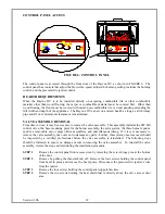
Page 8: ...rates Turning the HI LOW valve to HI allows the appliance to operate at its maximum Btu output rating Turning the HI LOW valve to LOW allows the appliance to operate at its minimum Btu output rating...

Page 9: ...ulator assembly within 3 feet 90cm horizontally from the center line of the regulator M 18 in Clearance under veranda porch deck or balcony 30 in minimum for vinyl clad soffits A vent shall not termin...

Page 10: ...Other tools or equipment may be required depending on site specific conditions Various open end wrenches including 7 16 9 16 and crescent wrenches as needed Various nut drivers and torx drivers as req...

Page 11: ...following steps present log installation instructions WARNING IMPROPER LOG PLACEMENT INSIDE THE FIREBOX CAN CAUSE IMPROPER FUEL BURN EXCESSIVE CARBON MONOXIDE a colorless odorless toxic gas PRODUCTIO...

Page 12: ...rner is designed not only to hold the embers but also to produce a small flame that creates the burning ember effect The middle and rear burner are designed to produce the fire and turn the larger log...

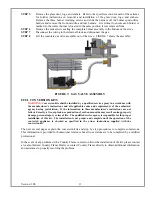
Page 13: ...REMOVAL From time to time it may be necessary to remove the valve assembly This assembly includes the SIT 820 control valve the base mounting plate for the burner assembly the pilot system the three b...

Page 14: ...s instructions and all applicable codes and requirements of the authorized agency having juristriction If the information in these manufacturer s instructions are not followed exactly a fire explosio...

Page 15: ...V 4623 55 DMS NG Front Orifice Spud Middle Spud Orifice 1 BV 4624 45 DMS NG Middle Orifice Spud Rear Spud Orifice 1 BV 4625 40 DMS NG Rear Orifice Spud Conversion Label 1 35 0500 02 Conversion LP to N...

Page 16: ...r the correct gas pressures corresponding to the conversion kit being used WARNING This conversion kit shall be installed by a qualified service agency in accordance with the manufacturer s instructio...

Page 17: ...riately sized drill bit as an air shutter gauge Pass the gauge through both sides of the air shutter adjust and lock the shutter removing the gauge when finished making adjustments STEP 11 Use a 3 8 i...

Page 18: ...c igniter should be in a parallel plane to the pilot flame diffuser body Each time the igniter button is pressed a blue arc should occur from the piezoelectric igniter to the pilot flame diffuser body...

Page 19: ...THE BATTERY ANNUALY SEALED VENTING SYSTEM The Bayvue DV is designed for a sealed vent system This means that all flue connections including all seams and joints are to be sealed with high temperature...

Page 20: ...yvue DV product is approved for side wall vent or vertical vent through a roof Only Simpson Dura Vent chimney components or Selkirk Model Direct Temp chimney components may be used with this product S...

Page 21: ...well as galvanized finish The galvanized pipe and fittings are used for concealed locations such as attics or spaces where corrosion is a factor such as above the roof line Decorative plated trim kits...

Page 22: ...ermination 36 CF 11044 982 Snorkel Termination 14 CF 11040 984 Horizontal Square Termination CF 11041 983 Vertical Termination CF 11050 950 Vinyl Siding Standoff CF 11000 This standard termination kit...

Page 23: ...eplace inside home air with fresh outside air so many times an hour This air exchange system is balanced to the number of occupants and the fuel burning appliances located in the home If additional co...

Page 24: ...ed as an unrestricted space EXAMPLE 2 A room will have a direct vent fireplace installed that has an input rating of 26 200 Btu H An adjoining room connected by a doorless passageway contains a 60 000...

Page 25: ...nting Graphs provided on the following pages will aid the installer in determining the proper relationship between vertical and horizontal side wall venting These Venting Graphs should assist the inst...

Page 26: ...e center of the 10 inch square hole Attach the horizontal vent termination to the exterior wall with the four wood screws provided as shown in FIGURE 13 Before attaching the Vent Termination to the ex...

Page 27: ...BLE Version 1 0h 26 HOT WOOD SCREWS Vinyl Siding Bolt Terminal to vinyl standoff Vinyl Siding Standoff Apply Sealant to all Four Sides Screws Wall Penetration Heat Shield Wall Thimble Duravent Part 94...

Page 28: ...al rise required for a specific horizontal run FIGURE 17 HORIZONTAL VERTICAL VENT SYSTEM Version 1 0h 27 HORIZONTAL TOP FLUE INSTALLATION Round Support Box Wall Thimble Standard Horizontal Terminal 90...

Page 29: ...rsection draw a vertical line to the bottom of the graph 4 Select the indicated dimension and position the unit in accordance with the same Example 1 Natural Gas Graph DV 46 If the vertical dimension...

Page 30: ...MODEL DV 30 A vent shall not terminate A Within six feet 1 8 meters of a mechanical air supply inlet to a building B Above a utility meter within three feet 1 meter horizontally of its vertical center...

Page 31: ...Bayvue DV appliance is 34 feet when measured from the top of the appliance to the bottom of the Flue Cap The maximum number of 45 degree elbows permitted for a vertical installation is four elbows In...

Page 32: ...onto the top of the chimney system Note 1 For multi story vertical installations a ceiling fire stop Part 963 is required at the second floor and any subsequent floors The opening should be framed to...

Page 33: ...ncy of homeowner use of this product Country Flame recommends that a certified service technician perform an annual check up on an appliance prior to the start of each heating season Follow the genera...

Page 34: ...ttern or the pilot light flame pattern contact a local authorized Country Flame Dealer or certified technician FIGURE 21 STANDING PILOT GLASS CLEANING FREQUENCY Before the first use and after first fo...

Page 35: ...eramic Kera Lite GLASS REPLACEMENT 1 Turn off gas valve 2 Unlock four door latches 2 each side refer to door installation section and FIGURE 23 WARNING Once door latches are unhooked nothing holds doo...

Page 36: ...nt of rope cement to hold rope gasket in place 9 Reinstall assembly FIGURE 24 to stove body Close door latches securing assembly to Bayvue DV 10 The door assembly is a sealed unit Refer to door seal s...

Page 37: ...working order No lubrication of any part is required in the Bayvue DV appliance It is recommended that at a minimum annual inspection of the venting system be conducted by a certified professional At...

Page 38: ...rate the stove with the door open Correct Bayvue DV operation requires the door assembly be mounted to the stove and locked during all operations except during maintenance FIGURE 23 DOOR INSTALLATION...

Page 39: ...ar When any one or all of the burners are removed ensure they are marked from the spot they were taken and returned to the same position The burners are NOT interchangeable and must be placed in the p...

Page 40: ...irection of travel of the relief valve A spring provides tension to hold the relief valve against the body of the stove Relief plates should be free to slide on the tracks provided shown in FIGURE 26...

Page 41: ...e pilot adjust or the manifold pressure can cause damage to the SIT 820 control valve and should only be accomplished by a certified professional For lighting instructions refer to the section on firs...

Page 42: ...ovided by law All electrical components such as but not limited to blowers wiring switches speed controls thermo disc switches igniters burners and gas valves are covered under Country Flame Technolog...

Page 43: ...ame is not large enough Pilot flame is not engulfing the generator thermocouple Thermocouple shorting Faulty valve Faulty thermocouple Purge the gas line Fill the tank Turn up the pilot flame Gently t...

Page 44: ...gas pressure Remove and clean Adjust regulator Not heating properly Not enough or too slow Dirt in the burner orifice Wrong orifice Too much draft Improper gas pressure Underrated Appliance Remove an...

Page 45: ...Orifice Spud Natural Gas 46 000 BTUH 45DMS BV 4625 Rear Orifice Spud Natural Gas 46 000 BTUH 40DMS BV 4626 Front Orifice Spud Liquid Propane 46 000 BTUH 69DMS BV 4627 Middle Orifice Spud Liquid Propan...

Page 46: ...ard On Off Remote Kit GC 3934 Snap Disc Thermostat GC 3989 Ember Material All parts for the Bayvue DV product can be purchased by contacting a local authorized Country Flame Dealer In the event there...

Page 47: ...turn the ON PILOT OFF control knob counterclockwise to ON 2 3 4 5 6 7 Turn off all electrical power to the Bayvue DV Open the Bayvue DV bottom panel to expose the gas control panel Push in on the ON P...

Page 48: ...SAFETY LABEL Version 1 0h 47...

Reviews: