FRANÇAIS
25
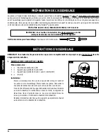
2. ASSEMBLAGE DU CHARIOT
Pièces nécessaires :
2 x Renfort pour jambe du chariot
(#4)
1 x Jambe du chariot gauche - avant
(#5)
1 x Jambe du chariot gauche - arrière
(#6)
1 x Jambe du chariot droite - avant
(#7)
1 x Jambe du chariot droite - arrière
(#8)
8 x Rondelle
(#B)
8 x Écrou
(#C)
8 x Vis longue
(#D)
4 x Vis longue
(#E)
4 x Écrou
(#F)
Installation
:
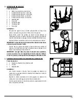
• Desserrez les quatre écrous à oreilles préassemblés sur chacun des
pieds, en laissant un espace de 8 à 9 mm (0,3 à 0,35 pouces).
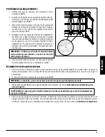
• Notez l’ordre correct des jambes du chariot comme indiqué sur
l’illustration 2A. Fixez une jambe du chariot aux supports de jambe du
chariot à l’aide de deux vis longues, de deux rondelles et de deux écrous.
• Répétez la même installation pour les trois autres jambes du chariot.
IMPORTANT : Les jambes du chariot doivent être installés dans le bon
ordre pour pouvoir replier l’unité.
• Ensuite, fixez un support de jambe du chariot entre deux jambes de
chariot, sur le côté court de l’unité, à l’aide de deux vis longues et de
deux écrous. Remarque l’illustration 2B.
IMPORTANT : Lorsque toutes les pièces du chariot sont assemblées,
revenez en arrière et serrez complètement tout le matériel. Veillez à
ne pas trop serrer, car cela pourrait endommager ou dénuder les fils.
3. FIXATION DES POIGNÉES DU CHAMBRE DE COMBUSTION
Pièces nécessaires :
2 x Poignée du chambre de combustion
(#2)
4 x Vis
(#G)
4 x Rondelle
(#H)
Installation
:
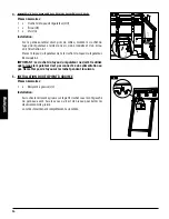
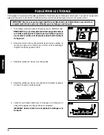
• Avec l’unité restante à l’envers, fixez la poignée du chambre de
combustion au panneau latéral du chambre de combustion à l’aide de
deux vis et rondelles.
• Répétez la même installation de l’autre poignée du chambre de
combustion sur le côté opposé du chambre de combustion.
• Une fois que le chariot est bien fixée, soulevez soigneusement l’unité
dans une position verticale.
Attach the leg support brackets (11) using screws (E) and nuts (F).
Attach the handles (4) from underneath using screws (G), washers (H) and nuts (F).
Further install the rgulator hose hook (5) with a screw (G) and a nut (F).
3
2
H
H
G
G
screws (A).
Eight of the nuts (closest to the hot plate) are pre installed for your convenience.
Attach the legs (6), (7), (8) and (9) in the order as shown to the leg bracket installed
in STEP 1 using screws (D), washers (B) and nuts(C) as shown below.
2A
screws (A).
Eight of the nuts (closest to the hot plate) are pre installed for your convenience.
Attach the legs (6), (7), (8) and (9) in the order as shown to the leg bracket installed
in STEP 1 using screws (D), washers (B) and nuts(C) as shown below.
5
D
D
C B
C
C
B
D
D
B
B
C
6
7
8
Attach the leg support brackets (11) using screws (E) and nuts (F).
Attach the handles (4) from underneath using screws (G), washers (H) and nuts (F).
Further install the rgulator hose hook (5) with a screw (G) and a nut (F).
2B
F
F
F
F
E
E
4
4
E
E

