ENG
LISH
7
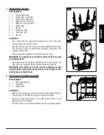
2. ASSEMBLING THE CART
Parts Required:
2 x Cart Leg Brace
(#4)
1 x Left Cart Leg - Front
(#5)
1 x Left Cart Leg - Back
(#6)
1 x Right Cart Leg - Front
(#7)
1 x Right Cart Leg - Back
(#8)
8 x Washer
(#B)
8 x Nut
(#C)
8 x Long Screw
(#D)
4 x Long Screw
(#E)
4 x Nut
(#F)
Installation:
• First, loosen the four preassembled wingnuts on each of the legs,
leaving a gap of 8-9mm (0.3-0.35 in).
• Note the correct order of Cart Legs as shown in illustration 2A. Attach
one Cart Leg to the Cart Leg Brackets using two long screws, two
washers, and two nuts.
• Repeat the same installation for the other three Cart Legs.
IMPORTANT: Cart Legs must be installed in correct order to be able
to collapse the unit.
• Next, fasten one Cart Leg Brace between two Cart Legs, on the short
side of the unit, using two long screws and two nuts. Note 2B.
IMPORTANT: Once all the parts of the cart are assembled, go back
and fully tighten all hardware. Be careful not to over-tighten, as that
could damage or strip threads.
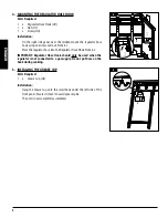
3. ATTACHING THE FIREBOX HANDLES
Parts Required:
2 x Firebox Handle
(#2)
4 x Screw
(#G)
4 x Washer
(#H)
Installation:
• With the unit remaining upside-down, attach the Firebox Handle to
the side panel of the Firebox using two screws and washers.
• Repeat the same installation of the other Firebox Handle on the
opposing side of the Firebox.
• Once the cart is secure, carefully lift the unit into an upright position.
Attach the leg support brackets (11) using screws (E) and nuts (F).
Attach the handles (4) from underneath using screws (G), washers (H) and nuts (F).
Further install the rgulator hose hook (5) with a screw (G) and a nut (F).
3
2
H
H
G
G
screws (A).
Eight of the nuts (closest to the hot plate) are pre installed for your convenience.
Attach the legs (6), (7), (8) and (9) in the order as shown to the leg bracket installed
in STEP 1 using screws (D), washers (B) and nuts(C) as shown below.
2A
screws (A).
Eight of the nuts (closest to the hot plate) are pre installed for your convenience.
Attach the legs (6), (7), (8) and (9) in the order as shown to the leg bracket installed
in STEP 1 using screws (D), washers (B) and nuts(C) as shown below.
5
D
D
C B
C
C
B
D
D
B
B
C
6
7
8
Attach the leg support brackets (11) using screws (E) and nuts (F).
Attach the handles (4) from underneath using screws (G), washers (H) and nuts (F).
Further install the rgulator hose hook (5) with a screw (G) and a nut (F).
2B
F
F
F
F
E
E
4
4
E
E


