NEVER LEAVE A FAN
UNATTENDED WHILE
OPERATING OR WHILE
CONNECTED TO A POWER
SOURCE
HVF Air Circulator User’s Manual
For customer support, call 1-866-641-4540 www.TractorSupply.com
3
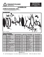
Replacement Parts
Item #
Description
Part Number
1
Logo Plate
95-043-0365
2
Front Grille
95-032-0160
3, 4, 5
Fan Blade Assembly
95-003-0615
6
Frame Washer
95-024-0250
7
Frame-Support L
95-024-0265
8
Main Circle Tube
95-024-0280
9
Top Washer
95-024-0290
10
Rear Grille
95-032-0260
11
Motor
95-030-0525
12
Switch Holder
95-031-0310
13
Switch
95-031-0120
Item #
Description
Part Number
14
Switch Cover
95-031-0510
15
Cord Bushing
95-026-0165
16
Control Knob
95-027-0110
17
Front Foot
95-023-0220
18
Rear Foot
95-023-0230
19
Frame-Support R
95-024-0275
20
Swivel Spacer
95-050-0180
21
Lower Support Frame
95-024-0245
22
Power Cord
95-026-0240
23
Capacitor
95-004-0225
24
Wall Mount Kit
95-078-0100
If the Wall Mount Kit is applied, the
installer MUST be certain that the
support bracket is mounted to a minimum of a 2x4”
stud, and that it is able to support 50 pounds
continuously
.
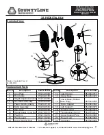
1. Remove 1 screw from each Frame Support L and R
(Items 7 and 19).
2. Slide Frame Support L and Frame Support R into
Support Frame (Item 21) and line up holes for screw.
3. Re-attach screw to Frame Support L and Frame
Support R.
20” FLOOR FAN
1
2
3
4
5 6 7 8
9
10
11
12
13 14
15
16
23
22
17
18
19
20
21
Figure 1: Exploded View of CL-20F-DDF
24
Installation and Assembly
(requires Phillips head screwdriver)
Exploded View
WARNING


