background image

Tables 

11

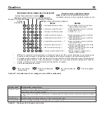
Charging

Battery status

Pump status

AC power

Silenced audible alarm

System Alert

= Excessive battery drain;

Battery will not take a charge***;

Charge time monitor – 1;

Reversed battery connections;

Wrong battery voltage;

Charge time monitor – 2;

Failed pre-qualification test – 2**;

Failed pre-qualification test – 1**;

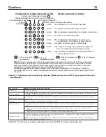
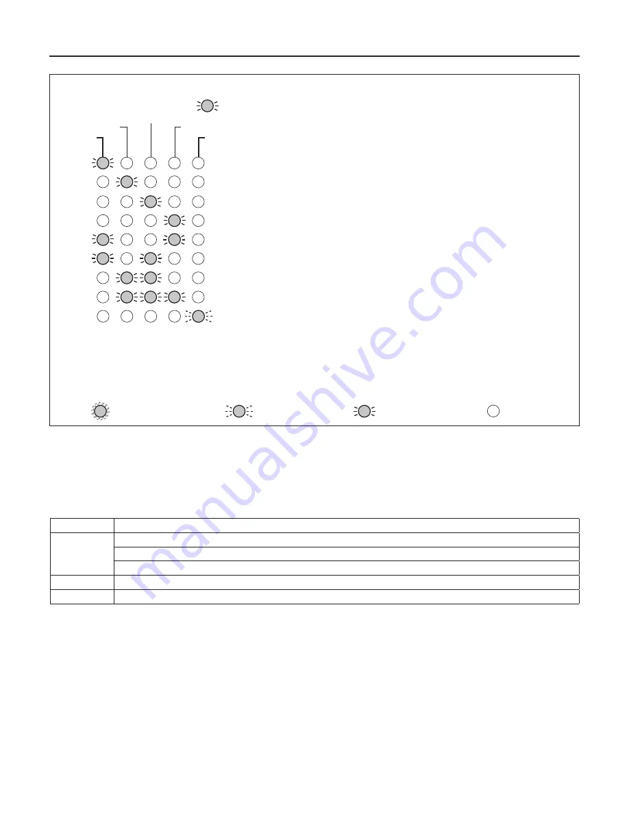
LED Error Code Display

Condition

Action

Error Condition and Corrective Action

NOTE: When the ‘System Alert’ LED is flashing,
look for one of the following error conditions.

NOTE: If your AC power is off and the unit is dead (no LEDs lighted, no audible alarm, pump isn’t running), 


check for reversed battery connections to the charger/controller.

** 

Charger was charging at a very low level to try to bring a dead battery back to life, but the battery took too long


to charge. Try resetting the charger once or twice (push the ‘System Test’ and ‘Silence Alarm’ buttons at the same


time to reset the charger).

*** 

Thermal Runaway condition

LED is Flashing (Slow)

=

LED is OFF

LED is ON Continuously

=

=

5766 0108

= Battery Charge is Below 20%;

Stop pump, allow battery to charge (AC must be on)

Replace battery with a new 12V lead-acid battery

Check battery for damage to cells; replace battery

C to + and – to –.*

Replace battery with a new 12V lead-acid battery

Check battery for damage to cells; replace battery 

Replace battery with a new 12V lead-acid battery

Replace battery with a new 12V lead-acid battery

Pump will shut down, battery is not charging. Replace
battery. 

LED is Flashing (Fast)

=

TABLE IV – Error Code Displays (LEDs Flashing)

Control Button:

Result of Pushing Button:

System Test

Pump starts and all LEDs light up.
Will reset the ‘Pump Status’ LED.
When pushed with the ‘Silence Alarm’ button, the Charger/Controller microprocessor resets and error code resets.

Silence Alarm

Toggle; Prevents the audible alarm sounding. Press and release to reset.

Flood Light

Toggles the flood light on the Charger/Controller on and off.

TABLE V – Control Button Functions

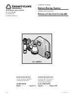
Summary of Contents for CL1800DC

Page 1: ...WI 53115 Phone 800 535 4950 Fax 800 526 3757 www tractorsupply com Installation Operation Parts For further operating installation or maintenance assistance Call 800 535 4950 English Pages 2 12 Instal...

Page 2: ...trical appliance submerged in water 4 Do not lift pump by electrical cord Risk of electric shock Can shock burn or kill Do not lift the pump by the electrical cord lift pump only by the discharge pipe...

Page 3: ...products used in commercial rental applications Sewage Pumps DO NOT return a sewage pump that has been installed to your retail store Contact CountyLine Customer Service Sewage pumps that have seen se...

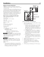
Page 4: ...or fuse box turn off the electrical power to the sump pump before beginning this installation Setup 1 Locate the high water level in your sump pit that is the water level at which the existing primar...

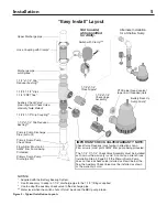
Page 5: ...Battery Backup System Use if necessary to adapt a 1 1 4 discharge pipe to the 1 1 2 fittings supplied Use to adapt the auxiliary check valve to the discharge pipe Water level when the switch shuts off...

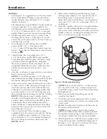
Page 6: ...pump assembly already includes a functioning check valve do not use the auxiliary check valve included in the BBU system You need one check valve between the primary pump and the tee to prevent backfl...

Page 7: ...ure 4 and connect the second battery in the same manner Connect the positive battery lead red to the positive Charger Controller terminal red Connect the negative battery lead black to the negative te...

Page 8: ...lack on the charger and the positive on the battery must connect to the positive on the charger Reversing the battery connections will cause the System Alert and Silenced Audible Alarm LEDs to flash 3...

Page 9: ...size so it will fit in the battery box maximum size 13 long 7 wide and 10 high 330 2mm x 177 8mm x 254mm including terminals and supply enough voltage for full performance Battery Maintenance Risk of...

Page 10: ...ashing LED Battery pre qualification test is running TABLE II Operating Code Displays LEDs Lighted Continuously or Flashing Control LED Continuous Illumination Indicates Normal Operation AC Power AC p...

Page 11: ...the same time to reset the charger Thermal Runaway condition LED is Flashing Slow LED is OFF LED is ON Continuously 5766 0108 Battery Charge is Below 20 Stop pump allow battery to charge AC must be on...

Page 12: ...ple 1 1 4 NPT x Close 1G Check Valve Assembly 1 1 4 FNPT x 1 1 4 FNPT 2 DC Backup Pump PS17 118 3 Vertical Float Switch Package PS198 269REP 4 Charger PS217 1512 5 Battery Case Complete PS17 1512 6 AC...

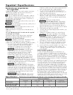
Page 13: ...recomienda usar un disyuntor a tierra GFCI con cualquier aparato el ctrico sumergido en agua 4 No levante la bomba por el cord n el ctrico Riesgo de choque el ctrico Puede provocar choque quemadura o...

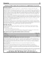
Page 14: ...ilizados en aplicaciones comerciales o de alquiler Bombas cloacales NO devuelva una bomba cloacal que se haya instalado a su tienda minorista Comun quese con el Departamento de Atenci n al Cliente de...

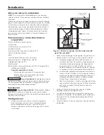
Page 15: ...instalaci n Configuraci n 1 Ubique el nivel de agua alto en su foso de recogida es decir el nivel del agua en la cual se enciende la bomba de sumidero presente primaria consulte la Figura 1 Marque est...

Page 16: ...e descarga superior Empalme de manguera con abrazaderas Trozo cortado de la tuber a de descarga Manguito reductor corredizo de 1 1 2 x 1 1 4 Te de 1 1 2 x 1 1 2 corredizo x 1 1 4 FNPT Empalme corrediz...

Page 17: ...de la bomba primaria ya incluye una v lvula de retenci n que funciona no use la v lvula de retenci n auxiliar incluida en el sistema BBU Usted necesitar una v lvula de retenci n entre la bomba primari...

Page 18: ...as use el segundo juego de bornes consulte Figuras 4 y conecte la segunda bater a de la misma manera Conecte el conductor positivo de la bater a rojo al borne positivo del Cargador Control rojo Conect...

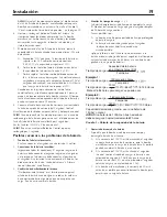
Page 19: ...tivo negro en el cargador y el positivo en la bater a se debe conectar al positivo en el cargador Si se invierten las conexiones de la bater a los diodos emisores de luz de Alerta del sistema y Alarma...

Page 20: ...mm x 177 8 mm x 254 mm incluyendo los bornes y suministre suficiente tensi n para un rendimiento completo Mantenimiento de la bater a Riesgos de quemaduras Las patillas de las bater as los terminales...

Page 21: ...lterna CA se ilumina siempre que el sistema est enchufado en un circuito de corriente alterna CA activo Cuadro II Visualizaciones de los c digos de operaci n Diodos emisores de luz DEL continuamente i...

Page 22: ...uevo acumulador cido de plomo de 12V Cambiar la bater a por un nuevo acumulador cido de plomo de 12V Medida La bomba se apagar la bater a no est cargando Cambiar la bater a DEL est centelleando r pido...

Page 23: ...lvula de retenci n 1 1 4 FNPT x 1 1 4 FNPT 2 Bomba de respaldo de CC PS17 118 3 Paquete de interruptor de flotador vertical PS198 269REP 4 Cargador PS217 1512 5 Caja de la bater a completa PS17 1512...

Page 24: ......

Reviews: