INSTALLATION MANUAL
INSTALLATION
29
Tub mount assembly
Note:
If the cover was supplied with the ground
anchoring option, skip to the
ground anchoring
assembly section
.
1)
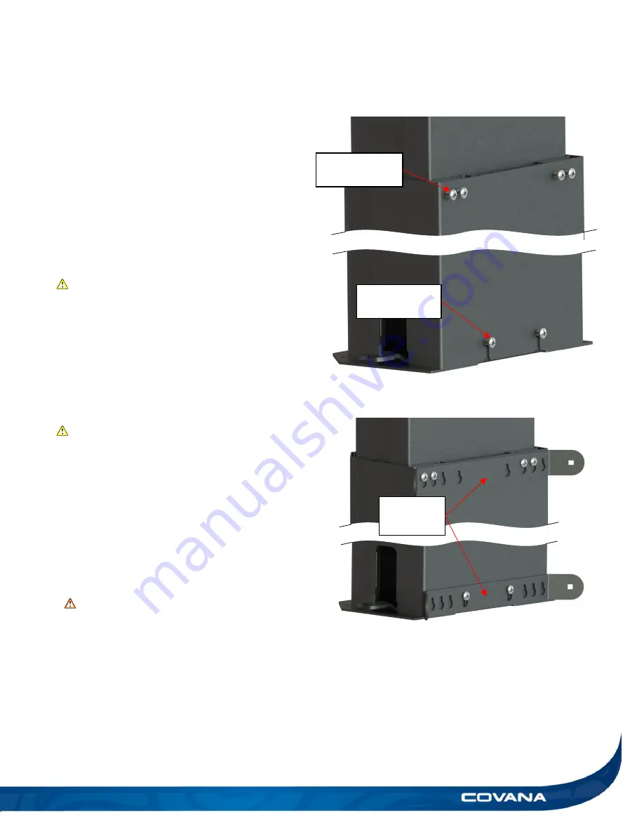
Loosen the four top 1/4-20 x 1/2 in. Phillips
screws so you have an approx. 1/4 in. (6.35 mm)
gap between the heads of the screws and the
outer sleeve. (Figure 59)
CAUTION
•
Do not fully remove the screws. Failure to
follow this instruction will cause damage to the
post assemblies.
2)
Untighten the two bottom 1/4-20 x 1/2 in. Phillips
screws to have an approx. 1/4 in. (6.35 mm) gap
between the heads of the screws and the sleeve.
(Figure 59)
CAUTION
•
Do not fully remove the screws. Failure to
follow this instruction will cause damage to the
post assemblies.
3)
Slide both the top and bottom sleeve brackets on
the appropriate screws. Ensure the sleeve
brackets are well centered with the post
assembly. (Figure 59)
4)
Tighten all six screws. (Figure 60)
WARNING
Do not overtighten any hardware. Failure to
follow this instruction might damage the paint
or the hardware itself.
5)
Repeat steps 1 to 4 for the second post
assembly.
Sleeve
brackets
1/4-20 x 1/2 in.
Phillips screws
1/4-20 x 1/2 in.
Phillips screws
Figure 59
Figure 60
Summary of Contents for C-HOR
Page 1: ...Revision 13 2018 04 23...
Page 53: ...INSTALLATION MANUAL APPENDIX 53 APPENDIX...
Page 54: ...54 APPENDIX INSTALLATION MANUAL Wiring diagram North America 60 Hz 120 VAC Operator...
Page 55: ...INSTALLATION MANUAL APPENDIX 55 Wiring diagram Europe 50 Hz 220 VAC Operator...


