INSTALLATION MANUAL
INSTALLATION
31
3)
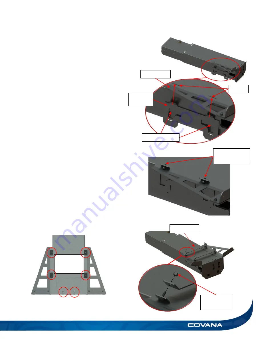
Insert the side support bracket hook in the notch
of the outer sleeve. (Figure 64)
4)
Slide on the post bracket on the side support
bracket using the slots as guide. (Figure 64)
5)
Place the 1/4-20 x 3/4 in. carriage bolts hanging
in their square holes as it will be harder to do
later. (Figure 65)
6)
Repeat steps 3 to 6 for the other side of the
sleeve.
7)
Reinstall the 1/4-20 x 1/2in. Phillips screws
removed in step 2, this will hold the brackets in
place while remaining pieces are installed.
(Figure 63)
8)
Link the right and left support brackets with the
linkage bar with the included 1/4-20 nylon hex
lock nuts and carriage bolts already installed.
Leave these untightened. (Figure 66)
9)
Repeat steps 2 to 8 for second assembly.
10)
Tighten all bolts and nuts installed from steps 3
to 8 for both post assemblies. (Figure 67)
11)
Flip both posts back on their feet.
Tighten all
bolts and
nuts.
Figure 67
Linkage bar
1/4-20 nylon
hex lock nut
Figure 66
1/4-20 x 3/4 in.
carriage bolts
Figure 65
slots
Insert hook here
Figure 64
post bracket
support
bracket
Summary of Contents for C-HOR
Page 1: ...Revision 13 2018 04 23...
Page 53: ...INSTALLATION MANUAL APPENDIX 53 APPENDIX...
Page 54: ...54 APPENDIX INSTALLATION MANUAL Wiring diagram North America 60 Hz 120 VAC Operator...
Page 55: ...INSTALLATION MANUAL APPENDIX 55 Wiring diagram Europe 50 Hz 220 VAC Operator...


