INSTALLATION MANUAL
INSTALLATION
35
10) Repeat steps 8 an 9 on the opposite side.
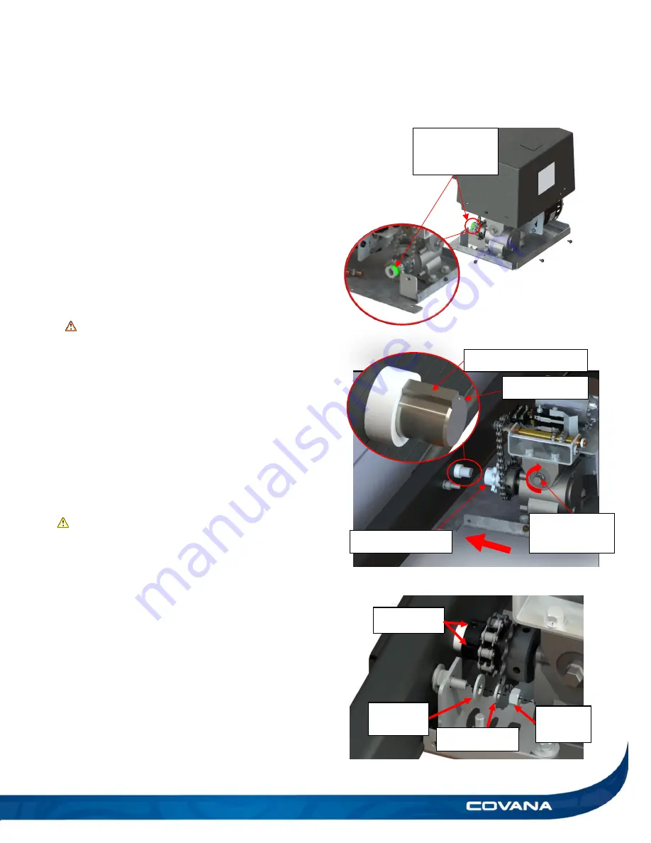
11) Remove the four slotted screws at the bottom of
the operator and remove the cover. Do not
discard these screws. (Figure 78)
12) Install the 3/16-3/16 x 5/8 in. square key into the
motorside
’s input shaft’s keyway. (Figure 79)
13)
Remove the tape on the operator’s sprocket.
14) Untighte
n the set screws of the operator’s
sprocket. (Figure 80)
15) Align the keyways of the input shaft and
operator’s sprocket together by turning the hex
shaft of the gearbox. (Figure 79)
WARNING
Do not turn more than 20 turns. If more turns are
required, the lower limit switch will have to be
reset. See
Limit switch adjustment section
.
16) Insert the motor-
side’s input shaft into the
sprocket. (Figure 79)
17) Fasten the operator to the two bolts from the
motorside with two 5/16 in. flat washers, 5/16 in.
lock washers and 5/16-18 hex nuts. (Figure 80)
18) Tighten both set screws in the sprocket. (Figure
80)
CAUTION
•
Do not overtighten the set screws or use
any power tools as it could damage some
components.
Remove the
tape on the
sprocket.
Figure 78
Hex shaft of
the gearbox
3/16-3/16 x 5/8 in. key
Operator sprocket
Input shaft
Figure 79
Flat
washer
Lock washer
5/16-18
hex nut
Set screw
Figure 80
Summary of Contents for C-HOR
Page 1: ...Revision 13 2018 04 23...
Page 53: ...INSTALLATION MANUAL APPENDIX 53 APPENDIX...
Page 54: ...54 APPENDIX INSTALLATION MANUAL Wiring diagram North America 60 Hz 120 VAC Operator...
Page 55: ...INSTALLATION MANUAL APPENDIX 55 Wiring diagram Europe 50 Hz 220 VAC Operator...


