14
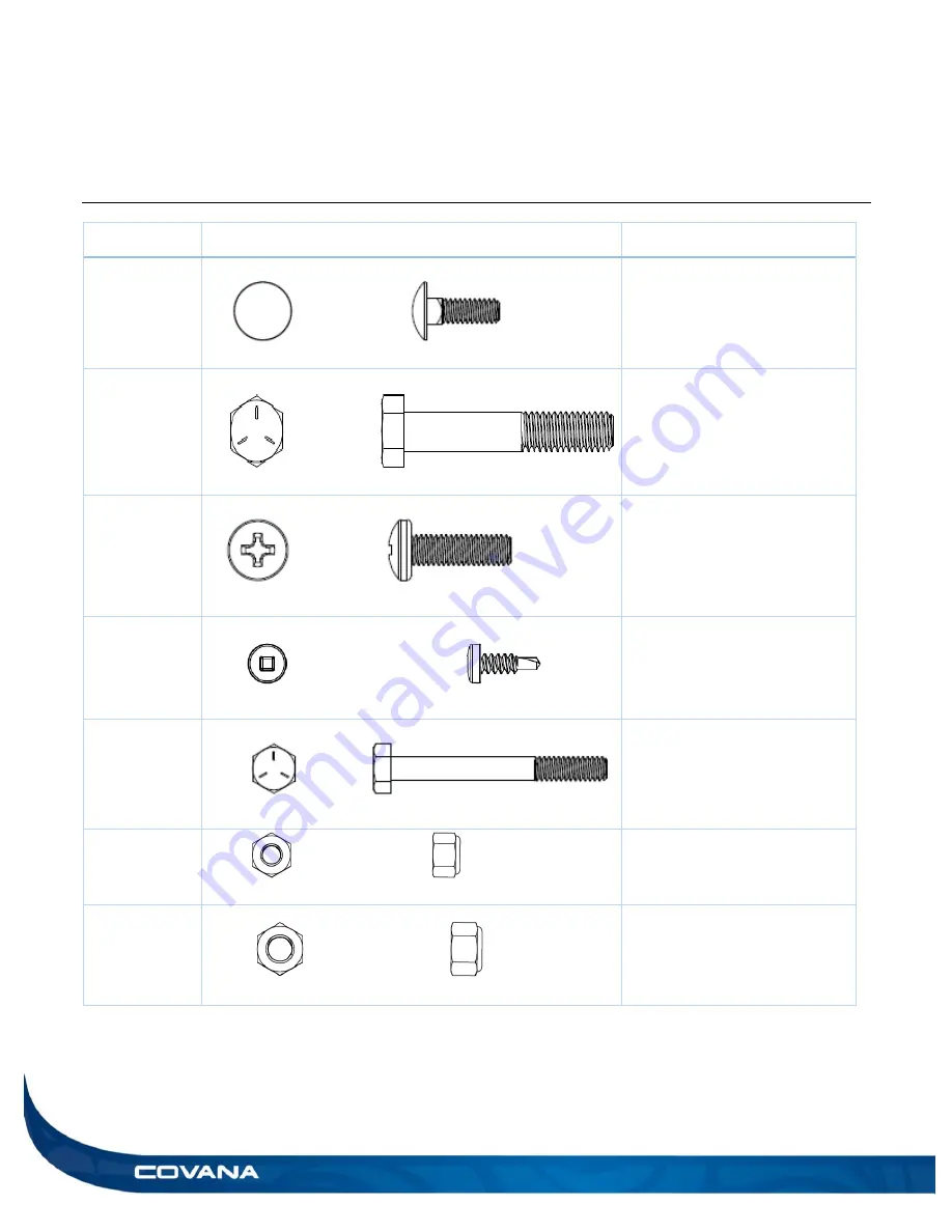
HARDWARE IDENTIFICATION TABLE
INSTALLATION MANUAL
HARDWARE IDENTIFICATION TABLE
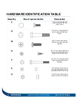
Quantity
Visual representation
Description
4
1/4
″-20 x 3/4″ carriage bolt
used to assemble the front
frame cut-out.
17
5/16
″-18 x 2″ hexagonal bolt
used to assemble the lower
frame.
19
M6 x 20 mm screw used to
hold the inner and outer shell
together.
17
#8 x 1/2
″ self-drilling Robertson
screw used to fasten the inner
sleeve to the Covana cover.
4
1/4
″-20 x 2 1/4″ hexagonal bolt
used to assemble the feet of
the posts.
8
1/4
″″-20 Nylon- insert locknut.
Used to assemble the feet of
the posts and the front cut-out.
17
5/16
″-18 nylon-insert locknut
used to connect the U-frames.
Summary of Contents for Evolution GHSC
Page 1: ...1 INSTALLATION MANUAL Revision 1 2017 05 29 Revision 2 2017 11 10...
Page 49: ...INSTALLATION MANUAL APPENDIX 49 APPENDIX...
Page 50: ...50 APPENDIX INSTALLATION MANUAL Wiring diagram North America 60 Hz 120 VAC Operator...
Page 51: ...INSTALLATION MANUAL APPENDIX 51 Wiring diagram Europe 50 Hz 220 VAC Operator...
Page 53: ...INSTALLATION MANUAL INSTALLATION CHECKLIST Customer copy 53...
Page 56: ...56 INSTALLATION MANUAL...


