32
INSTALLATION
INSTALLATION MANUAL
20) Unscrew the 3/8
″-24 x 1″ Allen bolt with a 7/32″
(5.5 mm) socket on the top of all four jack
assemblies. Put these parts in safe place.
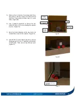
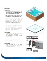
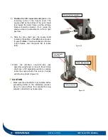
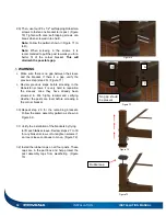
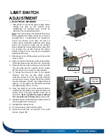
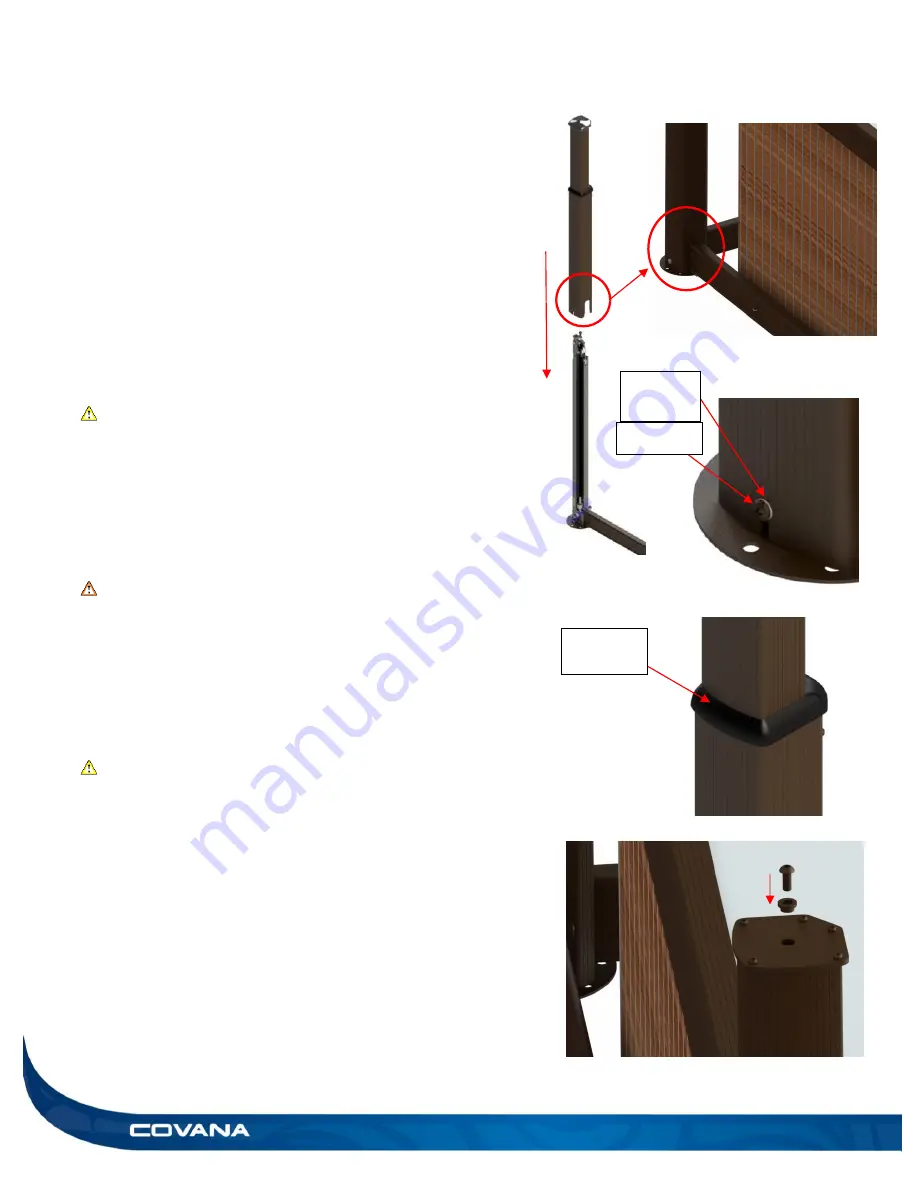
21) Slide the sleeves over all four jacks. (Figure 64)
Be sure to align the opening at the bottom of the
sleeves with the U-frames attached. (Figure 63)
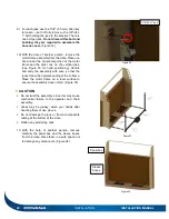
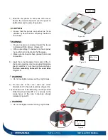
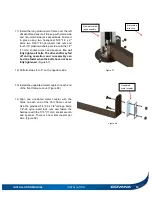
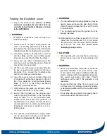
22) Screw in the Phillips M6 x 20 mm screws at the
bottom of all four sleeves. (Figure 65)
CAUTION
Be sure that the nylon washer is on the outside
of the outer sleeve. (Figure 65)
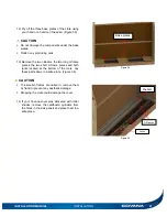
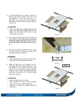
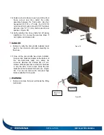
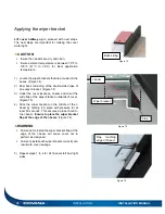
23) Make sure the all-weather seal on each post is
slid all the way down against the outer sleeve.
(Figure 66)
WARNING
Failing to properly position this part may cause
serious damage to post mechanism.
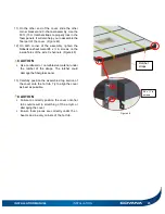
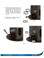
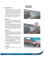
24) Install the 3/8
″-24 x 1″ Allen bolt with a 7/32″ (5.5
mm) socket, with the narrow part of the bushing
facing downwards for each post. (Figure 67)
CAUTION
Make sure that the wider part of the bushing is
facing upwards when you screw in the 3/8
″-24 x
1
″ Allen bolt.
Be sure the hole in each top plate is aligned with
the jack assembly’s threads before installing the
screw.
Figure 65
M6 screw
1/4
″
Nylon
washer
Figure 63
Figure 64
Figure 66
All-weather
seal
Figure 67
Summary of Contents for Evolution GHSC
Page 1: ...1 INSTALLATION MANUAL Revision 1 2017 05 29 Revision 2 2017 11 10...
Page 49: ...INSTALLATION MANUAL APPENDIX 49 APPENDIX...
Page 50: ...50 APPENDIX INSTALLATION MANUAL Wiring diagram North America 60 Hz 120 VAC Operator...
Page 51: ...INSTALLATION MANUAL APPENDIX 51 Wiring diagram Europe 50 Hz 220 VAC Operator...
Page 53: ...INSTALLATION MANUAL INSTALLATION CHECKLIST Customer copy 53...
Page 56: ...56 INSTALLATION MANUAL...

