INSTALLATION MANUAL
INSTALLATION
35
Testing the Evolution cover
1) Plug in the Covana cover.
(Have a certified
electrician complete the electrical hook-up
and refer to the Electrical Diagrams section
in the APPENDIX).
WARNING:
All electrical connections must be done by a
certified electrician.
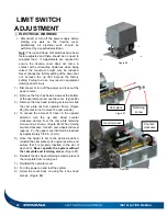
2) Ensure there is no object directly above the
cover or in its lifting path while performing this
test. Refer to the instructions in the
Limit Switch
Adjustment
section
if adjustments are required.
3) Use the key switch to lift it about 8 in. (20 cm)
and stop. Make sure the cover is lifting equally
(there are no corners higher than the others).
4) Lower the cover down completely and make
sure the cover is touching the pieces of foam all
around the hot tub perimeter.
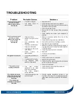
5) Lift the cover all the way up and pay attention
for any unusual sounds (metal screeching or
knocking). If so, consult the
Troubleshooting
section
or contact your local dealer.
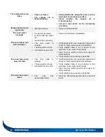
6) Lower the cover and ensure it stops at the point
of contact with all the foam spacers on the hot
tub. If not, adjust the corner brackets (Follow
steps 27 to 30 in the
Lifting mechanism
assembly (continued)
section.
7) Verify whether the posts are still level before
anchoring. Use the 48″ (122 cm) level.
8) Each of the four jacks on the Covana cover
must be properly anchored to the foundation
using at least one of the pre-drilled holes
located on the foot of each post. (Anchors not
supplied) Use a ¼ in. (6mm) concrete anchor for
concrete pads or a ¼ in. (6mm) lag bolt for wood
foundations, and insert a minimum of 1¼ in.
(30mm) deep.
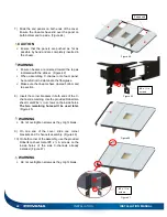
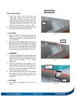
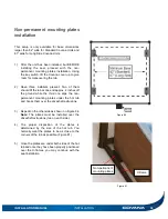
9) The optional non-permanent mounting plates
can be used when anchoring is not possible.
They are not designed for windy areas.
WARNING
The non-permanent mounting plates can only be
used in areas with low winds (less than 30 mph
(50 km/h) open and less than 45 mph (70 km/h)
in close position.
The non-permanent mounting plates must be
properly installed.
10) Permanently mount the key switch 5 ft. (1.5 m)
away from the hot tub and 5 ft. (1.5 m) above
the ground or floor at the key switch location
(See Figure 25).
Cut the power when
installing the key switch.
CAUTION:
When operating, the user must have a clear view
of the Covana cover and its surroundings at all
times.
WARNING:
Failure to permanently install the key switch as
previously indicated could cause serious injury
or even death. Only proper installation of the key
switch combined with the suggested procedures
and caution will reduce such risks. Product
certification will be lost if this guideline is not
respected.
Ensure that the base of the Covana cover is not
in a flood zone. Any damage caused by flooding
or water accumulation will not be covered under
the warranty.
Do not place the key switch in an area prone to
snow accumulation and water runoff.
Summary of Contents for Evolution GHSC
Page 1: ...1 INSTALLATION MANUAL Revision 1 2017 05 29 Revision 2 2017 11 10...
Page 49: ...INSTALLATION MANUAL APPENDIX 49 APPENDIX...
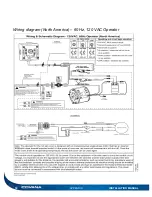
Page 50: ...50 APPENDIX INSTALLATION MANUAL Wiring diagram North America 60 Hz 120 VAC Operator...
Page 51: ...INSTALLATION MANUAL APPENDIX 51 Wiring diagram Europe 50 Hz 220 VAC Operator...
Page 53: ...INSTALLATION MANUAL INSTALLATION CHECKLIST Customer copy 53...
Page 56: ...56 INSTALLATION MANUAL...

