page-
34
LEGENDX COVER
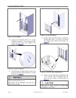
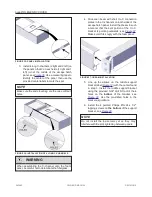
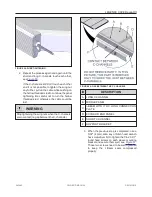
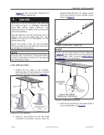
FIGURE 35: PANEL INSTALLATION
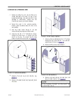
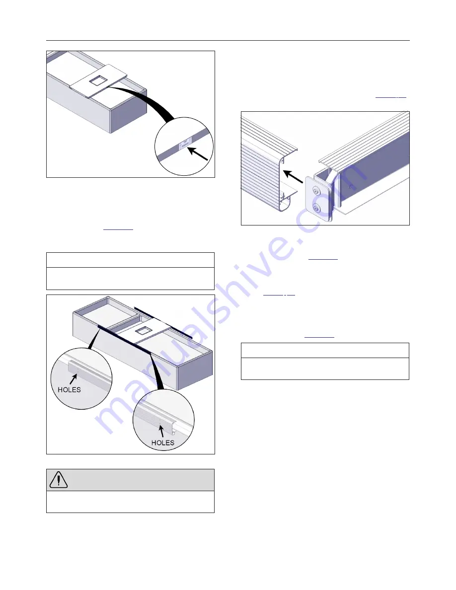
3. Install 4 long C-channels (2 right and 2 left) on
the panel so that 2 on each side (1 right and 1
left) join at the middle of the escape hatch
panel, see
. Use a measuring tape to
identify the center of the panel, then use the
provided center labels to mark the spot.
NOTE
Make sure the ends touching are the ones without
holes.
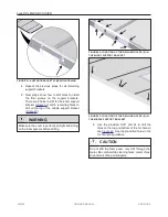
FIGURE 36: INSTALLATION OF 4 LONG C-CHANNELS
WARNING
When assembling the C- channel onto the foam
panel, be careful not to delaminate the fiberglass.
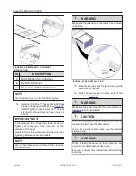
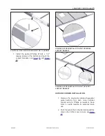
4. Slide one I-beam with short I to C connection
plates in the C-channels on both sides of the
escape hatch panel. Install the I-beam in such
a manner that the bent portion of the I to C
bracket is pointing outwards, see
.
Make sure it fits snugly with the foam panel.
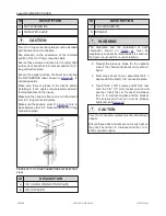
FIGURE 37: I-BEAM INSTALLATION
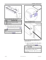
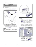
5. Line up the arrows on the middle support
bracket label (
) with the center found
in step 3. Install the middle support bracket
using the provided 5/32" drill bit to drill the 4
holes on the
bottom
of the bracket, see
. Use the pre- drilled holes in the
bracket as guidance.
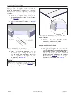
6. Install the 4 painted Philips #10- 24 x 1/2"
tapping screws on
the bottom
of the support
bracket, see
NOTE
Do not install the top screws yet as they may
interfere with the joint tightening between panels.
243462
OWNER'S MANUAL
REVISION 2
Summary of Contents for LEGEND COVER
Page 1: ......
Page 2: ......
Page 16: ...page 14 LEGENDX COVER FIGURE 14 BATTERY SPECIFICATION LABEL 243462 OWNER S MANUAL REVISION 2...
Page 29: ...LEGENDX COVER page 27 HARDWARE IDENTIFICATION TABLE BAGS 243462 OWNER S MANUAL REVISION 2...
Page 70: ......
Page 74: ...page 72 LEGENDX COVER 243462 OWNER S MANUAL REVISION 2...
Page 82: ...page 80 LEGENDX COVER 243462 OWNER S MANUAL REVISION 2...

