LEGENDX COVER page-
41
).
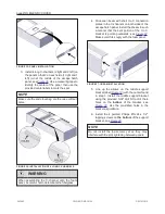
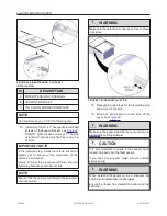
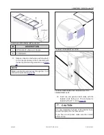
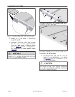
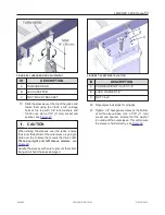
4. Use a #2 square screwdriver to secure the
corner bracket on the C-channel end by using
the #8 X 1/2" screws (
).
WARNING
Do not over tighten the screws as they might
break.
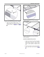
FIGURE 54: END C-CHANNEL INSTALLATION
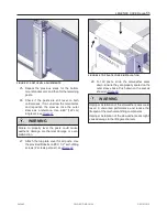
FIGURE 55: WIRE INSTALLATION
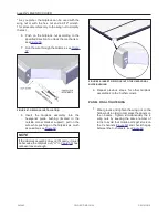
GRIPLOCK INSTALLATION
NOTE
Use hardware bag no. 50 for the following steps.
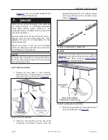
1. Install the Griplock completely into the
hexagonal coupling nut, see
2. Check that the Griplock is well tightened in
place.
3. Apply grease to the hollow threaded stud and
install it into the hexagonal coupling nut until it
reaches the Griplock extremity.
DANGER
The hollow threaded stud might be very sharp!
4. Ensure that the washer and the wing nut are
mounted at the minimum distance of d=1/2",
see
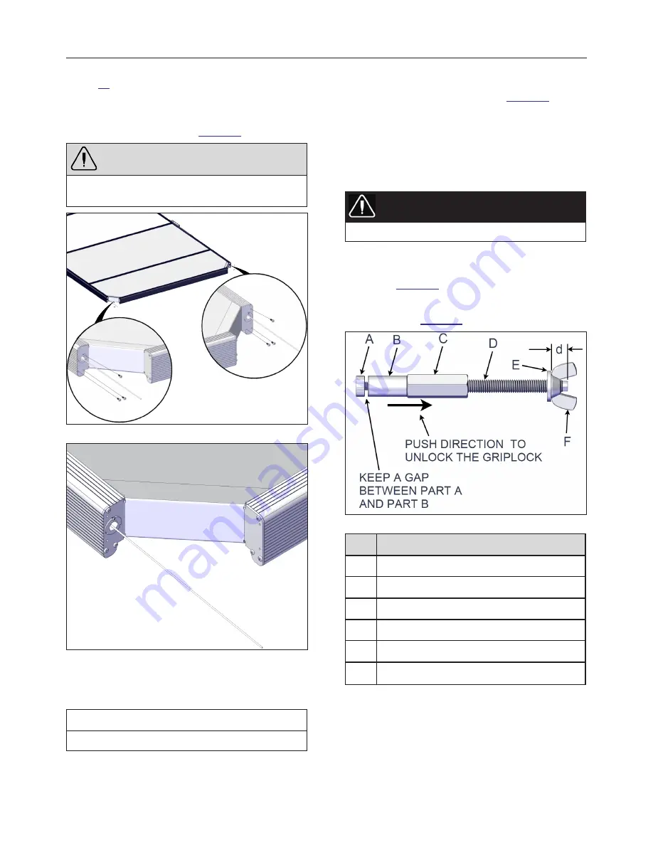
5. Keep a gap between part A and part B as
shown in
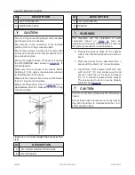
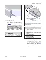
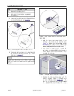
FIGURE 56: GRIPLOCK DEVICE
ID
DESCRIPTION
A
GRIPLOCK NUT
B
GRIPLOCK
C
HEX COUPLING NUT
D
HOLLOW THREADED STUD
E
FLAT WASHER
F*
WING NUT or 3/8-16 HEX. NUT
* The use of the hex. nut with a 9/16" wrench is
strongly recommended for the installation of the 24'
model. This procedure refers only to the wing nut to
simplify the text.
243462
OWNER'S MANUAL
REVISION 2
Summary of Contents for LEGEND COVER
Page 1: ......
Page 2: ......
Page 16: ...page 14 LEGENDX COVER FIGURE 14 BATTERY SPECIFICATION LABEL 243462 OWNER S MANUAL REVISION 2...
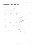
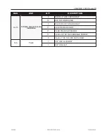
Page 29: ...LEGENDX COVER page 27 HARDWARE IDENTIFICATION TABLE BAGS 243462 OWNER S MANUAL REVISION 2...
Page 70: ......
Page 74: ...page 72 LEGENDX COVER 243462 OWNER S MANUAL REVISION 2...
Page 82: ...page 80 LEGENDX COVER 243462 OWNER S MANUAL REVISION 2...

