page-
50
LEGENDX COVER
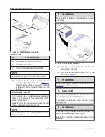
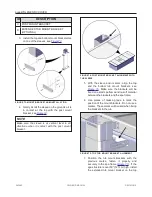
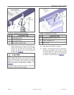
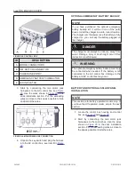
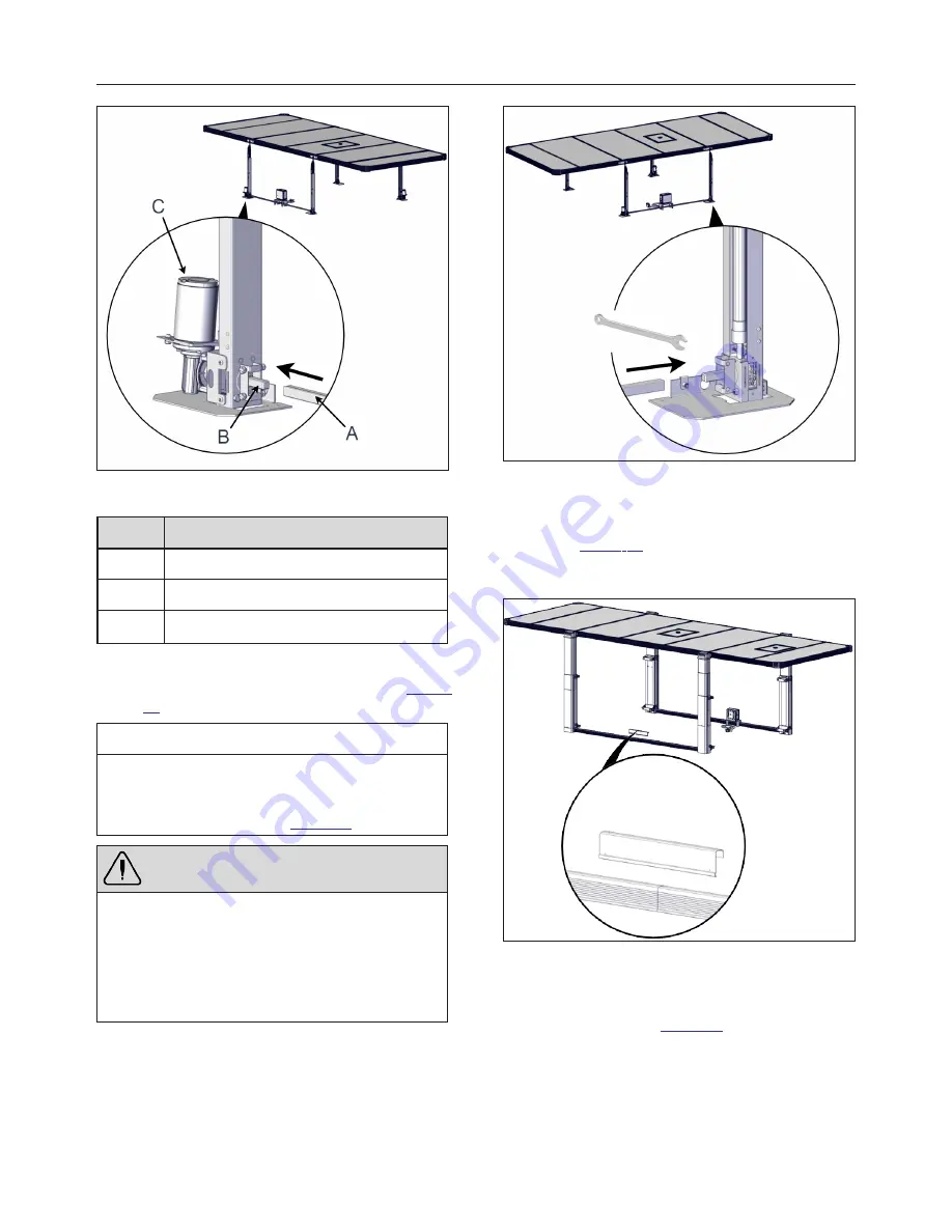
FIGURE 79: DRIVE SHAFT INSTALLATION ON THE
MOTOR SIDE
ID
DESCRIPTION
A
DRIVE SHAFT
B
SQUARE SHAFT
C
JACK MOTOR
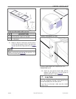
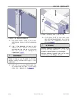
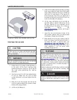
4. On the same spa side, install the drive shaft
onto the non-motorized jack shaft, see
.
NOTE
If the drive shaft does not line up with the non-
motorized jack shaft, the use of a 3/4" (19 mm)
wrench or adjustable wrench can help. Slightly
rotate the shaft as shown in
.
WARNING
While installing the drive shaft, check if it has not
been pulled out from the opposite side when
manipulating the part.
Do not twist the motorized jack with a wrench. This
jack contains a gearbox which could break when
stressed from the output.
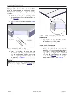
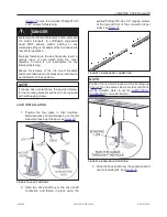
FIGURE 80: DRIVE SHAFT INSTALLATION ON THE NON-
MOTOR SIDE
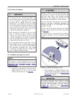
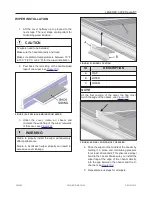
5. Slide 2 U-frames in the U-frame connection,
see
. Make sure the ends touching
are the ones without holes. Use a measuring
tape to center the U-frame connection.
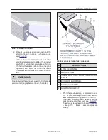
FIGURE 81: U-FRAME CONNECTION
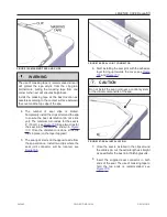
6. Use the provided 5/32" drill bit to drill the 4
holes on the top and front of the U- frame
connection, see
. Use the pre-drilled
holes in the U-frame connection as guidance.
243462
OWNER'S MANUAL
REVISION 2
Summary of Contents for LEGEND COVER
Page 1: ......
Page 2: ......
Page 16: ...page 14 LEGENDX COVER FIGURE 14 BATTERY SPECIFICATION LABEL 243462 OWNER S MANUAL REVISION 2...
Page 29: ...LEGENDX COVER page 27 HARDWARE IDENTIFICATION TABLE BAGS 243462 OWNER S MANUAL REVISION 2...
Page 70: ......
Page 74: ...page 72 LEGENDX COVER 243462 OWNER S MANUAL REVISION 2...
Page 82: ...page 80 LEGENDX COVER 243462 OWNER S MANUAL REVISION 2...


