background image

page-

88

LEGENDX COVER

Contact your local authorized Covana dealer for all service-related issues.

Made in Canada by Covana,

a division of the Canimex group

COVANA.COM

CANIMEX GROUP

PATENTED

CANADA 2,532,429

US 11/162,557

UK 0515168.3

AUSTRALIA 2006200251

The information in this manual was accurate at the time of print. The manufacturer reserves the right to

change or improve its product without prior notice.

243462

OWNER'S MANUAL

REVISION 2

Summary of Contents for LEGEND COVER

Page 1: ......

Page 2: ......

Page 3: ...LEGENDX COVER page 1 COVANA SPA COVER MANUFACTURER OWNER S MANUAL MANUAL NO 243462 243462 OWNER S MANUAL REVISION 2...

Page 4: ...ENDX COVER MANUAL NO 243462 First edition 11 11 2021 REVISION DESCRIPTION DATE 0 OWNER S MANUAL NEW RELEASE 11 11 2021 1 J Roller article code updated 11 23 2021 2 Warranty update 11 25 2021 243462 OW...

Page 5: ...L 12 AVOID DROWNING LABEL 13 DO NOT STEP ON THE COVER LABEL 13 MAINTENANCE INFORMATION LABEL 13 CENTER LABEL 13 TOP LABEL 13 BATTERY SPECIFICATION LABEL 13 GLOSSARY 15 INSTALLATION PROCEDURE 21 TOOLS...

Page 6: ...SING 74 PERIODIC MAINTENANCE TABLE 76 TECHNICAL SPECIFICATIONS 77 COVER SIDE VIEW 77 FRAME DIMENSIONS AND FOOT PRINT CONCRETE PAD RECOMMENDED 78 CONCRETE PAD OPTIONS 79 ELECTRICAL SPECIFICATIONS AC OP...

Page 7: ...we strongly recommend that you register your cover at the time of purchase to ensure an adequate follow up process In fact registering the cover allows us to quickly reach you in the unlikely event a...

Page 8: ...his manual in whole or in part written consent must be obtained from Covana Covana reserves the right to make changes without notice and without incurring any obligation SAFETY The cover was designed...

Page 9: ...ld raise smoothly and evenly Contact your Covana dealer if any unusual mechanical sound is heard during cover operations DOS l Remove the key from the key switch after operating the cover Store the ke...

Page 10: ...ll instructions in this manual and use only accessories and tools approved by Covana l Do not rotate or slide the cover using its edges This may damage the edge components l After removing a component...

Page 11: ...derground cable Not respecting this precaution may result in death or serious personal injury due to electrocution ELECTRICAL WARNING WARNING l To reduce the risk of electrical shocks the green colore...

Page 12: ...m away from the spa and 5 ft 1 5 m above the deck or ground level see Figure 2 l Make sure the user has a clear view of the cover when operating it l Furthermore the key switch must be located in an...

Page 13: ...hese labels are always visible and should never be removed RISK OF ELECTROCUTION For AC operated models only This label warns you about the risk of electrocution It is located on the AC control box FI...

Page 14: ...is label shows the important technical specifications It is located on the control box of the AC operated model NOTE This label also shows the serial number of the cover FIGURE 6 FOR BATTERY OPERATED...

Page 15: ...ABEL This label displays the web site where you can get more information on maintenance procedures It is located on one of the C channels FIGURE 11 MAINTENANCE INFORMATION LABEL CENTER LABEL This labe...

Page 16: ...page 14 LEGENDX COVER FIGURE 14 BATTERY SPECIFICATION LABEL 243462 OWNER S MANUAL REVISION 2...

Page 17: ...etween the cover and the spa preventing the entry of contaminants into the spa or the loss of heat from the spa Contour seal installation clip Contour seal installation clips are temporary parts used...

Page 18: ...the C channels on the side to the ones in front and back Drive shaft The drive shaft transmits the power between the jack assemblies Escape hatch The escape hatch is a removable panel and part of the...

Page 19: ...e control box manages the movement of the unit Control box housing for battery operated model only The control box housing contains the control box and the battery pack of the cover I beam The I beams...

Page 20: ...e C Channel It prevents the over tightening of the I to C connection plates Key switch The key switch is used to operate the cover Foam spacer The foam spacer are used for the installation process to...

Page 21: ...between the center C channel to the C channel on either side It clips and is screwed on the top and bottom It also acts as the link between the cover and the inner sleeve of the post via the cover mo...

Page 22: ...There is one tub mount bracket located at the top of the outer sleeve and one at the bottom for every post Extended tub mount bracket Optional The extended tub mount bracket is optional for spas with...

Page 23: ...are the foundation and carefully read the following recommendations SPA LOCATION CONSIDERATIONS Make sure the future cover location is not subject to the water downpours or debris falling Make sure th...

Page 24: ...er or some cover s support dedicated slabs must be provided see Technical Specifications section Those independent supports must respect the same level variation as mentioned below The foundation must...

Page 25: ...ws holding the front cover 5 screws per side and 3 on the top You might need a step ladder to reach the top screws see Figure 16 FIGURE 16 CARDBOARD REMOVAL 5 Remove the front cover and discard see Fi...

Page 26: ...arefully slide the jack box out Some parts can be damaged if the jack box is pulled out too roughly FIGURE 21 JACK BOX REMOVAL 12 Remove the jack assembly by unscrewing the Robertson 8 x 1 5 screws Th...

Page 27: ...OAMS 16 With the help of another person lay the crate horizontally on its back There should be one person on each side of the crate see Figure 25 WARNING The crate is heavy you may require a third per...

Page 28: ...locks that retain the panels Remove the fiberglass panels from the crate and keep them in a safe location see Figure 27 WARNING Panels are fragile Handle with care they can easily be scratched or dama...

Page 29: ...LEGENDX COVER page 27 HARDWARE IDENTIFICATION TABLE BAGS 243462 OWNER S MANUAL REVISION 2...

Page 30: ...t bracket installation 17 1 4 20 x 1 BUTTON HEAD SOCKET CAP SCREW SS 18 8 No 40S or 40M Corner installation 4 GROOVE FLANGE HEX SHAFT BUSHING 13 4 x 3 16 ROUND HEAD SHEET METAL SCREW 42 8 32 X 1 2 PAN...

Page 31: ...on 9 5 16 18 x 2 HEX CAP SCREW 18 5 16 NYLON WASHER 9 5 16 18 HEX NYLON LOCK NUT 17 1 4 20 SS 316 HEX NUT 17 1 4 SS 316 LOCK WASHER 17 1 4 20 x 3 4 SS 18 8 CARRIAGE SCREW 8 1 4 20 x 1 SS 18 8 HEX CAP...

Page 32: ...NEL WITH ESCAPE HATCH E END C CHANNEL F I BEAM WITH I TO C SHORT CONNECTION PLATE G I BEAM WITH I TO C LONG CONNECTION PLATE H SHORT C CHANNEL I LONG SUPPORT BRACKET J MIDDLE SUPPORT BRACKET WARNING B...

Page 33: ...BEAMS This section shows how to assemble I to C plates on the I beams NOTE Use hardware bag no 10 for the following steps I TO C PLATE INSTALLATION ON THE I BEAMS 1 Install an I to C long connection p...

Page 34: ...o C long connection plate FIGURE 32 I TO C LONG CONNECTION PLATE SECTION VIEW ID DESCRIPTION A I TO C LONG CONNECTION PLATE B I TO C SPACER ID DESCRIPTION C FLAT WASHER 10 D SPACER WARNING The orienta...

Page 35: ...plate when it is installed FIGURE 34 WIRE INSTALLATION ID DESCRIPTION A I TO C LONG CONNECTION PLATE B FLAT WASHER 5 16 2 C SCREW 5 16 18 x 5 8 D WIRE FOR GRIPLOCK INSTALLATION E LOCK NUT 5 16 18 PANE...

Page 36: ...es in the C channels on both sides of the escape hatch panel Install the I beam in such a manner that the bent portion of the I to C bracket is pointing outwards see Figure 37 Make sure it fits snugly...

Page 37: ...le inserting the I beam in the C channel make sure it is always square with the C channel FIGURE 39 I BEAM INSTALLATION 7 Slide a middle panel on each side of the escape hatch panel Ensure the I beam...

Page 38: ...foam panel be careful not to delaminate the fiberglass Make sure the I beam has cleared the bottom and top section FIGURE 41 INSTALL BOTH I BEAMS WITH LONG I TO C CONNECTION PLATES FIGURE 42 TRIMMED...

Page 39: ...the middle of the spa Try to align the cover as best as possible see Figure 45 FIGURE 45 INSTALLATION OF THE COVER ON THE SPA CAUTION Failure to gently position the cover onto the spa could result in...

Page 40: ...t tightening between panels impossible NOTE Ensure that the screws run through the extension C channel slots WARNING Make sure the extension C channel is free to move in its slots FIGURE 47 SCREW INST...

Page 41: ...the wire passes through the I to C connection plate hole Figure 50 FIGURE 49 I BEAM INSTALLATION FIGURE 50 WIRE INSERTION THROUGH THE I TO C CONNECTION PLATE 18 Insert one end panel on both sides with...

Page 42: ...ews see Figure 52 FIGURE 52 HEXAGONAL GUIDE BUSHING INSTALLATION 2 Install the left and right corner bracket supports on each end C channel by using a 2 square screwdriver and the 8 X 1 2 screw see Fi...

Page 43: ...ase to the hollow threaded stud and install it into the hexagonal coupling nut until it reaches the Griplock extremity DANGER The hollow threaded stud might be very sharp 4 Ensure that the washer and...

Page 44: ...ire while pushing on the Griplock as much as possible see Figure 58 NOTE If the Griplock assembly does not fit easily it must be because the Griplock nut A in Figure 56 has not been loosen enough FIGU...

Page 45: ...lost WARNING Stop tightening the wing nuts when the C channels are in contact no gap between the C channels FIGURE 60 GAP BETWEEN THE C CHANNELS ID DESCRIPTION A LONG C CHANNEL B MIDDLE PANEL C I BEAM...

Page 46: ...G Make sure the cover is perfectly straight and sitting on the foam spacers before drilling FIGURE 62 LOCATION OF THE DRILLING HOLES 8 IN THE SHORT SUPPORT BRACKET FIGURE 63 LOCATION OF THE DRILLING H...

Page 47: ...TION ON THE MIDDLE SUPPORT BRACKET FIGURE 66 SCREW INSTALLATION ON THE SHORT SUPPORT BRACKET OUTSIDE CORNER INSTALLATION 1 Remove the previously installed hexagonal guide bushing from each corner brac...

Page 48: ...LATION 1 On the escape hatch check if the release mechanism is working well Make sure that the hatch arms are retracted when open and non retracted when closed see Figure 69 FIGURE 69 ESCAPE HATCH REL...

Page 49: ...r is centered on the spa The use of a measuring tape is required to reference your measures on all four sides 2 Next steps show how to install the tub mount brackets FIGURE 71 TUB MOUNT BRACKET INSTAL...

Page 50: ...LIGNMENT WITH THE SLEEVE 5 With the sleeve and its arms align the top and the bottom tub mount brackets see Figure 75 Make sure the brackets will be fixed on a solid spa frame and no soft material bet...

Page 51: ...he provided screws for the mounting brackets will need to be replaced with self tapping screws JACK INSTALLATION 1 Position the four jacks in their locations Motorized jacks should always be on the le...

Page 52: ...has not been pulled out from the opposite side when manipulating the part Do not twist the motorized jack with a wrench This jack contains a gearbox which could break when stressed from the output FIG...

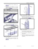
Page 53: ...FRAME INSTALLATION 10 Check if the drive shaft is still engaged on both ends Slip your fingers under the U frames to do this operation 11 Once the U frames are installed the jack lock screws located a...

Page 54: ...le pass near the U frame The electrical hook up will be explained further When connecting the motor harness you must hear a CLIC from the connector to confirm it has been installed properly WARNING En...

Page 55: ...uter sleeve is going to slide over the U frame that covers the drive shaft There are right and left sleeve models see Figure 88 Handle the sleeves with care to prevent them from being scratched otherw...

Page 56: ...1 4 flat washers on the outside Use a 1 4 lock washer and 1 4 20 nut on the inside Use a 5 32 4 mm drive and 7 16 11 mm spanner see Figure 89 and Figure 90 CAUTION The rounded tongue section of the br...

Page 57: ...l damage or even malfunction 27 Attach the top plate cover for all posts Use the provided Robertson 8 X 1 2 self drilling screws 2 screws per post seeFigure 92 FIGURE 92 TOP PLATE COVER INSTALLATION 2...

Page 58: ...e on the cover The wiring must comply with all applicable local electrical regulations l For AC operated model The Covana AC control box must be connected to a circuit that is protected by a dedicated...

Page 59: ...ry operated model skip to BATTERY AND OPTIONAL SOLAR PANEL INSTALLATION 1 Install the pre assembled control box and its holding bracket on one of the U frames between the two sleeves see Figure 94 WAR...

Page 60: ...cation The charger cuts the power once the battery is fully charged so you can keep the battery plugged on the charger DANGER The charger must always be indoors away from water Damage injury or death...

Page 61: ...TTERY B CIRCUIT BREAKER C KEY SWITCH D MOTOR E SOLAR PANEL 6 Slide the control box housing onto the U frame see Figure 99 7 Install the remainder of the wires as near as possible to the spa to hide th...

Page 62: ...s 6 Lift the cover all the way up or as high as possible without objects obstructing cover and pay attention to any abnormal sound metal grinding or knocking If so stop any movement consult the TROUBL...

Page 63: ...ver see Figure 101 WARNING Failure to properly install the wiper will adversely affect performance Failure to install each wiper properly can result in excessive cover leakage FIGURE 101 WIPER LOCATIO...

Page 64: ...the water by turning off the recirculation pump and then set the temperature of the spa water to be between 2 and 5 degrees under the ambient temperature Wait until the water has the ambient temperat...

Page 65: ...hown in Figure 106 Once the distribution is done stick the clips in place on the tape if applied 5 The seal joint starts on the opposite side from the spa entrance Install two clips where the seal joi...

Page 66: ...about 1 4 6 mm over the seal to ensure that the entire perimeter will make contact with the seal If you are satisfied raise the cover and remove the red plastic backing off the seal 10 Completely low...

Page 67: ...ated 9 You now have 30 seconds to reconnect the motors and set the upper height limit of the cover Use the key switch to raise the cover NOTE Every time that the height of the cover is changed the 30...

Page 68: ...way from the spa and 5 ft 1 5 m from the ground O The electrical portion of the installation was done by a certified electrician Electrical connections Limit switch adjustment sections O All parts sup...

Page 69: ...away from the spa and 5 ft 1 5 m from the ground O The electrical portion of the installation was done by a certified electrician Electrical connections Limit switch adjustment sections O All parts su...

Page 70: ......

Page 71: ...ns to center position when released off position 9 Always remove the key when the raising or lowering operations are completed and keep it in a safe location WARNING Users must bring the key in the sp...

Page 72: ...l power outlet 110 V North America 230 V Europe Figure 111 2 Plug the battery charger harness into the battery 3 A red light should appear to indicate that it is charging 4 Wait for the green light to...

Page 73: ...LEGENDX COVER page 71 WIRING DIAGRAM NORTH AMERICA 60 HZ 120 VAC CONTROL BOX 243462 OWNER S MANUAL REVISION 2...

Page 74: ...page 72 LEGENDX COVER 243462 OWNER S MANUAL REVISION 2...

Page 75: ...the cover Make sure to follow the spa manufacturer s guidelines during this step 8 Install a waterproof and watertight protection canvas over the control box WARNING Using any type of fabric or plast...

Page 76: ...nit will require the following greasing maintenance to ensure the best performance The internal jacks require yearly greasing Early in the fall season is the best time The Mobil Epic EP MOLY Grease is...

Page 77: ...limit see Figure 115 FIGURE 115 JACK RAISING 7 Spray grease on all the sliding parts and mechanical components of all jacks see Figure 116 FIGURE 116 SLIDING PARTS TO GREASE 8 Inspect the chains for...

Page 78: ...apor steam leakage X Verify the lifting mechanism by raising and lowering the cover X Verify the anchoring of the cover X Check if the escape hatch works properly X Test the GFCI X Check the tension o...

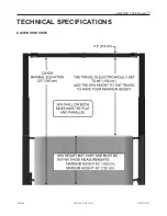
Page 79: ...LEGENDX COVER page 77 TECHNICAL SPECIFICATIONS COVER SIDE VIEW 243462 OWNER S MANUAL REVISION 2...

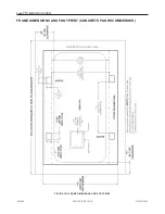
Page 80: ...page 78 LEGENDX COVER FRAME DIMENSIONS AND FOOT PRINT CONCRETE PAD RECOMMENDED FIGURE 118 FRAME DIMENSIONS AND FOOT PRINT 243462 OWNER S MANUAL REVISION 2...

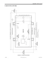
Page 81: ...LEGENDX COVER page 79 CONCRETE PAD OPTIONS FIGURE 119 CONCRETE PAD OPTIONS 243462 OWNER S MANUAL REVISION 2...

Page 82: ...page 80 LEGENDX COVER 243462 OWNER S MANUAL REVISION 2...

Page 83: ...fications to the electrical system Covana reserves the right to void the warranty if any modification is done without its approval ELECTRICAL SPECIFICATIONS BATTERY OPERATED MODEL Voltage 24 VDC Syste...

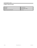
Page 84: ...page 82 LEGENDX COVER GENERAL SPECIFICATIONS Lifting speed 2 5 s 6 35 cm s Total weight 615 lb 280 kg 24 model Length of key switch electrical wire 25 ft 7 6 m 243462 OWNER S MANUAL REVISION 2...

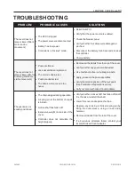
Page 85: ...the top of the cover l Verify whether any posts are obstructed l Use methanol to free ice buildup on posts l Apply grease on the post assemblies l Verify the relative position of the four posts See F...

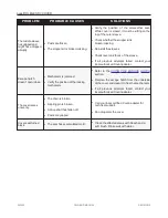
Page 86: ...tch doesn t open close l Mechanism is jammed l Verify the position of the locking mechanism l Refer to the USING THE ESCAPE HATCH section l Remove the escape hatch from the underside of the cover and...

Page 87: ...Freight charges related to replacement of parts under this warranty are paid for three 3 years from the original purchase date Discoloration and surface abrasions due to weathering will occur naturall...

Page 88: ...ks dust or sand undrained underground installations undrained surface flooding area or permanent water accumulation is not covered under the warranty LED LIGHT ASSEMBLY ELECTRICAL COMPONENTS 1 YEAR CO...

Page 89: ...d dealer which goes against this manual COVANA is not liable for any injury loss or damage direct or consequential arising out of the inability to use the COVANA Unit EXCLUSIONS l COVANA excludes from...

Page 90: ...a a division of the Canimex group COVANA COM CANIMEX GROUP PATENTED CANADA 2 532 429 US 11 162 557 UK 0515168 3 AUSTRALIA 2006200251 The information in this manual was accurate at the time of print Th...

Reviews: