OASIS COVER page-
35
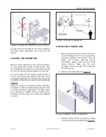
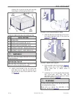
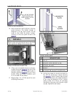
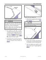
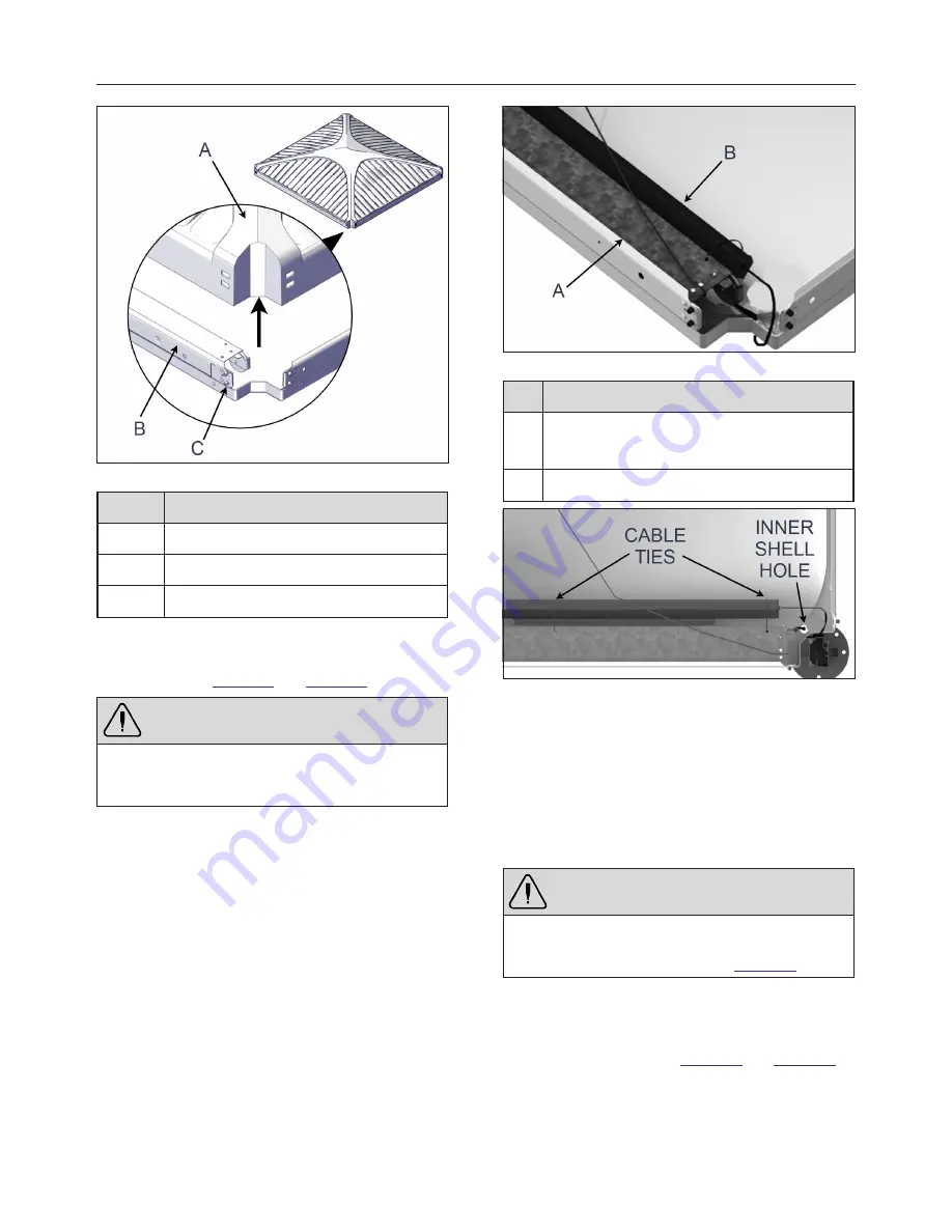
FIGURE 51: OUTER SHELL LIFTING
ID
DESCRIPTION
A
OUTER SHELL
B
STEEL FRAME
C
METAL INSERT
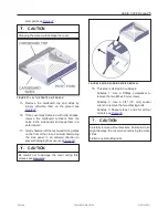
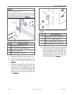
4. While holding the outer shell open, cut and
remove the two cable ties that hold the wire
guard see
and
.
WARNING
Completely remove both cable ties and discard
them. They could interfere with the CTS- 70
mechanism.
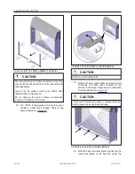
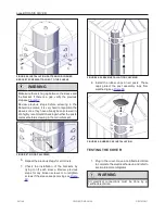
FIGURE 52: CABLE TIE REMOVAL
ID
DESCRIPTION
A
CTS-70
(CONTINUOUS TENSION SYSTEM)
B
WIRE GARD
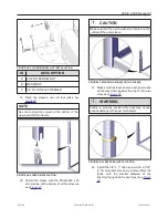
FIGURE 53: CABLE TIE LOCATIONS
5. Open the wire guard by ripping the plastic off.
The plastic bag includes two bottles of primer
and an alcohol swab; put those items in a
safe location.
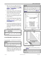
6. Gently remove the wire guard from the inner
shell. Let the wire guard hang down for the
next steps.
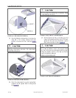
WARNING
Ensure the wire is clear of the inner and outer
shells before proceeding. The wire should only
hang from the inner shell hole see
.
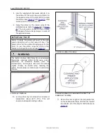
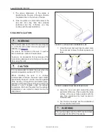
7. Clean the surface of the outer sleeve
positioned on the opposite corner of the light
button. Remove any dirt or contaminant and
dry the surface see
and
241146
OWNER'S MANUAL
REVISION 1
Summary of Contents for OASIS COVER
Page 1: ......
Page 2: ......
Page 54: ......
Page 59: ...OASIS COVER page 57 241146 OWNER S MANUAL REVISION 1...
Page 61: ...OASIS COVER page 59 241146 OWNER S MANUAL REVISION 1...
Page 63: ...OASIS COVER page 61 241146 OWNER S MANUAL REVISION 1...
Page 65: ...OASIS COVER page 63 241146 OWNER S MANUAL REVISION 1...

