page-
38
OASIS COVER
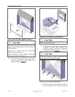
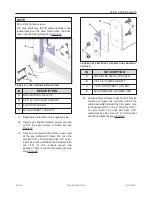
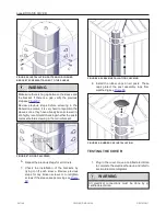
FIGURE 60: RED FILM REMOVAL
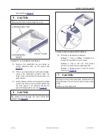
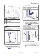
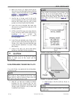
15. Now connect the bottom harness to the wire
guard connector. The bottom harness is
attached to the key switch cable. Cut the
cable tie that holds the bottom harness.
Connect it to the wire guard connector see
.
WARNING
Never remove the wire guard connector. This could
cause permanent damage to the wire harness.
FIGURE 61: WIRE GUARD CONNECTION
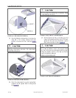
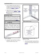
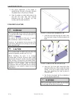
16. If the cover is completely lowered on the spa,
and the exiting wire (
) seems to have
sufficient tension and the magnetic plate is
properly positioned (
), move to next
section, lifting mechanism installation (part
2). If not, follow the next steps.
17. Repeat steps 1 to 3 of this section for outer
shell lifting instructions.
FIGURE 62: MAGNETIC PLATE
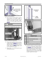
FIGURE 63: EXITING WIRE
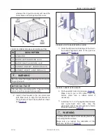
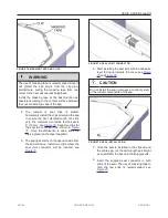
ID
DESCRIPTION
A
CTS-70
B
TENSION WIRE (GOING TO LED)
C
TENSION HOLDER
D
SCREW
E
EXITING WIRE (GOING TO OPERATOR)
18. Locate the screws for the tension holder on
the CTS- 70 (Continuous Tension System)
see
. Lightly unscrew them and pull
back the tension wire until a slight resistance
is felt. Once the resistance is felt, continue
pulling another inch. Check the protruding
wire going to the posts, and if the wire is tight
enough, retighten the set screws.
241146
OWNER'S MANUAL
REVISION 1
Summary of Contents for OASIS COVER
Page 1: ......
Page 2: ......
Page 54: ......
Page 59: ...OASIS COVER page 57 241146 OWNER S MANUAL REVISION 1...
Page 61: ...OASIS COVER page 59 241146 OWNER S MANUAL REVISION 1...
Page 63: ...OASIS COVER page 61 241146 OWNER S MANUAL REVISION 1...
Page 65: ...OASIS COVER page 63 241146 OWNER S MANUAL REVISION 1...

