page-
48
OASIS COVER
LIMIT SWITCH ADJUSTMENT
WARNING
Disconnect or turn off the power supply before
starting any work on the cover. All electrical work
should be performed by a qualified electrician.
NOTE
The up and down limit switches have been factory-
adjusted and there should be no need to readjust
them. If adjustments are required to ensure the
cover does not come in contact with surrounding
obstacles while being raised, the maximum height
may be reduced. Never change the factory setting
of the down limit nor increase the up limit beyond
the factory setting. Failing to do so may result in
equipment damage and/or injury.
1. Disconnect or turn off the power and lock out
the power source.
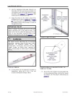
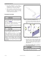
2. Remove the four slotted screws at the bottom
of the operator and remove the cover
.
FIGURE 79: REMOVE OPERATOR COVER
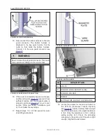
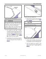
3. Remove the slotted retaining screw and slide
the cam plate out from operator frame see
. Be careful not to rotate the cam
wheels.
FIGURE 80: CAM PLATE REMOVAL
ID
DESCRIPTION
A
CAM PLATE
B
SLOTTED SCREW
C
DOWN-CAM WHEEL
D
UP-CAM WHEEL
241146
OWNER'S MANUAL
REVISION 1
Summary of Contents for OASIS COVER
Page 1: ......
Page 2: ......
Page 54: ......
Page 59: ...OASIS COVER page 57 241146 OWNER S MANUAL REVISION 1...
Page 61: ...OASIS COVER page 59 241146 OWNER S MANUAL REVISION 1...
Page 63: ...OASIS COVER page 61 241146 OWNER S MANUAL REVISION 1...
Page 65: ...OASIS COVER page 63 241146 OWNER S MANUAL REVISION 1...


