OASIS COVER page-
23
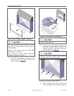
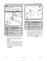
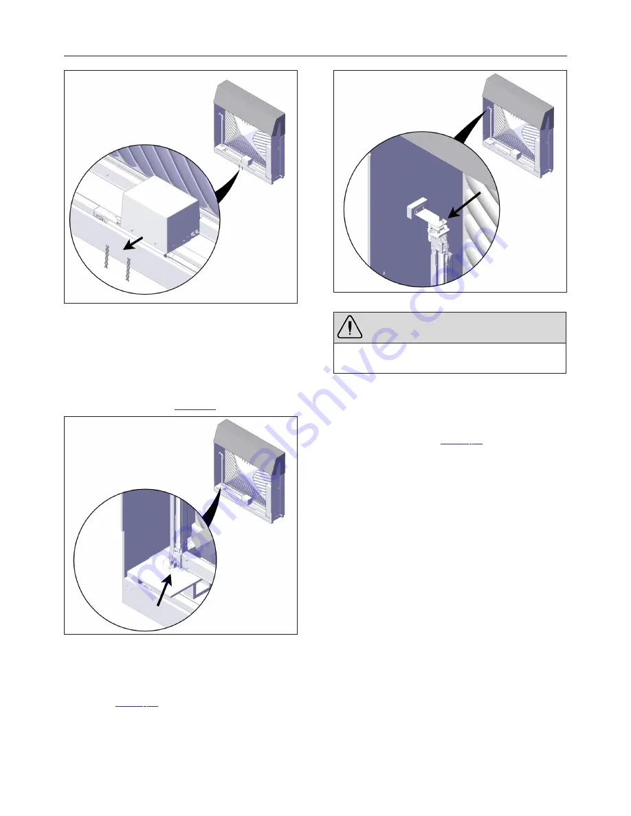
FIGURE 21: MOTOR FRAME ASSEMBLY REMOVAL
8. Reinstall the screws (2) on the operator
cover.
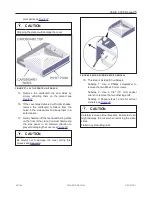
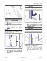
9. Use the 3/8″ (10 mm) socket wrench to
unscrew the hexagonal 1/4″ x 2″ lag bolts on
the bottom of both jacks. There are two lag
bolts per jack see
FIGURE 22: REMOVE BOTTOM LAG BOLTS ON JACKS
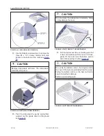
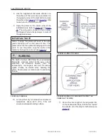
10. For each jack, use the 7/32″ (5.5 mm) Allen
key to loosen, but not fully remove, the 3/8″ x
1″ screw holding the jack to the top bracket
see
. There is one screw per jack.
Do not discard this screw and bushing; they
are required to assemble the cover.
FIGURE 23: LOOSEN TOP SCREW ON JACKS
WARNING
Do not remove the alignment bracket on the top of
the jack (red part).
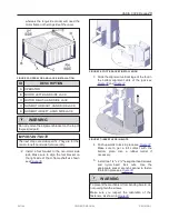
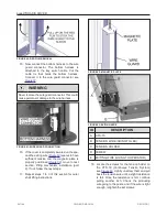
11. With the help of another worker, remove the
motor frame assembly
from the crate.
Position one hand under the horizontal portion
of the motor frame and the other hand on the
vertical jack see
. Handle and carry
the assembly with care, so that the jacks
follow the natural bending of the U- frame.
Install the motor frame assembly on a level
surface and make sure it will not fall.
241146
OWNER'S MANUAL
REVISION 1
Summary of Contents for OASIS COVER
Page 1: ......
Page 2: ......
Page 54: ......
Page 59: ...OASIS COVER page 57 241146 OWNER S MANUAL REVISION 1...
Page 61: ...OASIS COVER page 59 241146 OWNER S MANUAL REVISION 1...
Page 63: ...OASIS COVER page 61 241146 OWNER S MANUAL REVISION 1...
Page 65: ...OASIS COVER page 63 241146 OWNER S MANUAL REVISION 1...

