page-
40
OASIS COVER
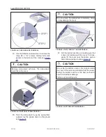
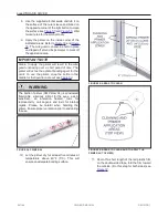
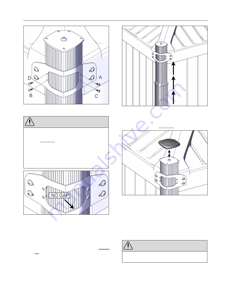
FIGURE 66: INSTALLATION PATTERN FOR CORNER
BRACKET SCREWS ATTACHED TO THE SLEEVE
WARNING
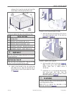
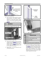
Make sure there is no gap between the sleeve and
the bracket. If there is a gap, verify the previous
step see
Review previous steps before screwing in the
Roberston screws; it is very hard to reposition the
sleeves once they have already been screwed in.
We highly recommend checking whether the posts
are level before screwing in the corner bracket.
FIGURE 67: NO GAP ALLOWED
6. Repeat the previous steps for all corners.
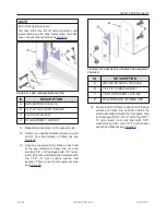
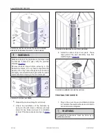
7. Check the installation of the brackets by
trying to lift each sleeve. Review previous
steps for any broken screws or to retighten
screws if the sleeve keeps moving see
.
FIGURE 68: SLEEVE INSTALLATION CHECKING
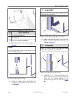
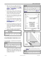
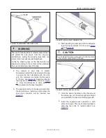
8. Install the rubber caps on all posts. These
caps protect the post assembly tops from
weathering see
FIGURE 69: RUBBER CAP INSTALLATION
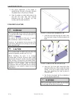
TESTING THE COVER
1. Plug in the cover. Have a certified electrician
to complete the electrical hook-up and refer to
section Electrical diagrams.
WARNING
All electrical connections must be done by a
certified electrician.
241146
OWNER'S MANUAL
REVISION 1
Summary of Contents for OASIS COVER
Page 1: ......
Page 2: ......
Page 54: ......
Page 59: ...OASIS COVER page 57 241146 OWNER S MANUAL REVISION 1...
Page 61: ...OASIS COVER page 59 241146 OWNER S MANUAL REVISION 1...
Page 63: ...OASIS COVER page 61 241146 OWNER S MANUAL REVISION 1...
Page 65: ...OASIS COVER page 63 241146 OWNER S MANUAL REVISION 1...

