MR Series 600K
User Manual
14
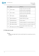
NO.
Name
Illustration
○
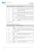
,2
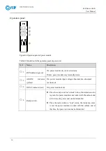
AC/DC indicator
On (green): the rectifier work normally.
On (red): the rectifier work abnormally.
○
,3
DC/AC indicator
On (green): the inverter work normally.
On (red): the inverter work abnormally.
○
,4
BYP. indicator
On (green): bypass output
On (red): bypass abnormal
○
,5
BATT. LOW indicator
On (green): battery low-voltage
○
,6
OVERLOAD indicator
On (red): overload
○
,7
ON combination button
Press the two buttons for 3s, the system will power on.
○
,8
OFF combination button
Press the two buttons for 3s, the system will power off.
○
,9
EPO emergency power off button
Press the button, the system will power outage
immediately.
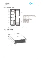
2.5 Structure Layout
The system layout diagram takes the power module full allocation as an example, please refer to the
real product.
Summary of Contents for MR Series
Page 1: ...Uninterruptible power supply COVER MR 600 kVA User manual ...
Page 2: ......
Page 10: ......
Page 36: ......
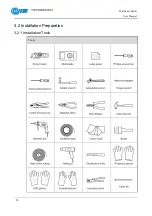
Page 38: ...MR Series 600K User Manual 28 3 2 Installation Preparation 3 2 1 Installation Tools Tools ...
Page 56: ......
Page 60: ...MR Series 600K User Manual 58 Figure4 4 Fault protection with no output Figure4 5 Shutdown ...
Page 61: ...MR Series 600K User Manual 59 Figure4 6 Exit parallel system Figure4 7 Bypass output ...
Page 62: ...MR Series 600K User Manual 60 Figure4 8 Battery INV output Figure4 9 Mains INV output ...
Page 89: ...MR Series 600K User Manual 87 Figure4 57 Confirm to power off ...


