MR Series 600K
User Manual
20
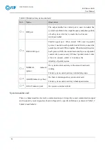
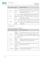
Table2-6 Illustration for system control card
NO.
Name
Illustration
○
,1
BSC port
The output double bus control port is used in double bus
system to synchronize the output frequency and phase position
of each system, which is to ensure the two bus can
switch each other.
○
,2
PARALLEL port
Parallel signal port. When several UPS used in parallel
system, it needs to use the parallel control wire to connect the
parallel port of each UPS in ringlike. When the parallel system
has N pieces of UPS, the connection needs N pieces of parallel
control wire to ensure every UPS has 2 parallel control wires
at least to connect, which is to enhance the
reliability of parallel system.
○
,3
NORMAL
indicator
(green)
On: system control card stay in the status of main card
running
Flicker: system control card stay in initializing status.
○
,4
ALARM indicator (yellow)
On: there is alarm signal in system control card.
Flicker: system control card stay in backup card status.
○
,5
FAULT indicator (red)
On: system control card fault
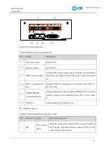
System monitor card
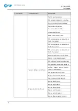
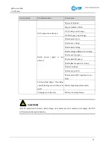
There is a human-machine interactive communication port, 4 input dry contact communication signal
and 4 output dry contact signal (as shown in Figure2-12), specific definition is as shown in Table2-7,
Table2-8 and Table2-9.
Summary of Contents for MR Series
Page 1: ...Uninterruptible power supply COVER MR 600 kVA User manual ...
Page 2: ......
Page 10: ......
Page 36: ......
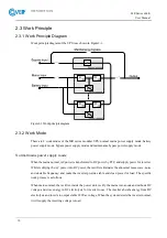
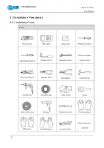
Page 38: ...MR Series 600K User Manual 28 3 2 Installation Preparation 3 2 1 Installation Tools Tools ...
Page 56: ......
Page 60: ...MR Series 600K User Manual 58 Figure4 4 Fault protection with no output Figure4 5 Shutdown ...
Page 61: ...MR Series 600K User Manual 59 Figure4 6 Exit parallel system Figure4 7 Bypass output ...
Page 62: ...MR Series 600K User Manual 60 Figure4 8 Battery INV output Figure4 9 Mains INV output ...
Page 89: ...MR Series 600K User Manual 87 Figure4 57 Confirm to power off ...


