MR Series 600K
User Manual
29
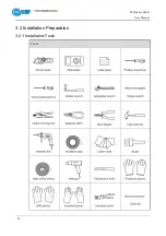
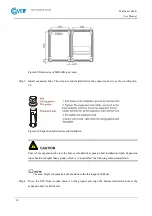
The installation tools should be with isolated operation to avoid electric shock.
3.2.2 Installation Environment
Do not install the UPS in the place where exceeds the provision of technology index (temperature:
0
℃~
40
℃
, relative humidity: 0
%~
95
%
).
It is strictly prohibit installing the UPS in the environment with metal conductive dust.
Do not install the UPS in the open air, and the installation environment should meet the provision
requirements.
Basic requirements for power supply:
−
Grounding preparation. Ensure that the grounding terminal is OK and the voltage between neutral
wire and grounding wire should not exceed 5V.
−
Before installation, please ensure that the AC input voltage and mains input wire capacity meet
the UPS requirements, and considering if there has current-carrying capacity descending caused
by wire aging.
−
The mains input voltage range of the UPS is 80~280VAC. The mains capacity should be greater
than the max. input power of the UPS.
−
The selected breaker should not with leakage current protection.
The installation environment of the UPS should be with good ventilation, and far away from water
source, heat source and inflammable and explosive objects. Avoid installing the UPS in the place
where has direct sunshine, dust, volatile gas, corrosive objects or high salt.
The optimal operating temperature for batteries is 20–30°C. Operating at temperatures lower than 20°C
will shorten the battery backup time, and operating at temperatures higher than 30°C will shorten the
battery lifespan.
Make sure that the external DC distribution circuit is configured with a bipolar disconnecting switch.
Summary of Contents for MR Series
Page 1: ...Uninterruptible power supply COVER MR 600 kVA User manual ...
Page 2: ......
Page 10: ......
Page 36: ......
Page 38: ...MR Series 600K User Manual 28 3 2 Installation Preparation 3 2 1 Installation Tools Tools ...
Page 56: ......
Page 60: ...MR Series 600K User Manual 58 Figure4 4 Fault protection with no output Figure4 5 Shutdown ...
Page 61: ...MR Series 600K User Manual 59 Figure4 6 Exit parallel system Figure4 7 Bypass output ...
Page 62: ...MR Series 600K User Manual 60 Figure4 8 Battery INV output Figure4 9 Mains INV output ...
Page 89: ...MR Series 600K User Manual 87 Figure4 57 Confirm to power off ...

