COVER serii NHS – User Manual
COMEX S.A.
13
Table 2-3 Description of the REPO interface pins
Pin
Description
Purpose
J4.1
EPO_NC
EPO is activated when disconnected from J4.2
J4.2
+
24V
+ 24V, voltage for connection to NC and NO
J4.3
EPO_NO
EPO is activated when connected to J4.2
Use external potential-free REPO circuit breakers using a normally closed (NC) or normally open (NO)
contact.
If you do not use the remote REPO switch, the J4.1 pin must be connected to J4.2 and the J4.2 pin
disconnected from J4.3.
警告
危 险
Warning
1. Using the EPO switch stops the operation of the rectifier, inverter and Bypass, and disconnects
the voltage at output.
2. As standard, pins J4.1 and J4.2 are connected to each other when the equipment is delivered.
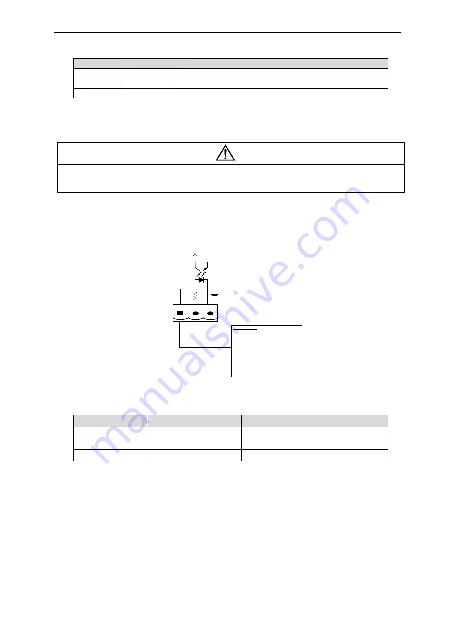
2.7.3. Genset interface
The J5 input connector is used to signal the connected generator. The connection of J5.2 pins with J5.1
(+ 24V) indicates that the system is operating from a power generator. The interface design and
description of connections are shown below.
J5
GEN
+24V
AUX-N.O.
AUX-N.O.
发电机
Figure 2-10 Genset signal interface
Table 2-4 Description of aggregate operation interface outputs
Pin
Description
Purpose
J5.1
+24V
+24V supply
J5.2
GEN
Signaling work from the aggregate
J5.3
GND
Ground
2.7.4. Output signal - bypass operation and indication of external bypass switch
position.
The J6 contact of the Dry Contact interface is an information signal indicating operation of the UPS in
the bypass mode. Output type - normally open (NO).
The J7 input connector is used to connect external information about the position of the external bypass
switch.
Generator


