COVER serii NHS – User Manual
COMEX S.A.
14
B
C
B
_
D
R
V
B
C
B
_
C
O
N
T
J6
J7
B
C
B
_
O
N
L
+24V
+24V
+24V
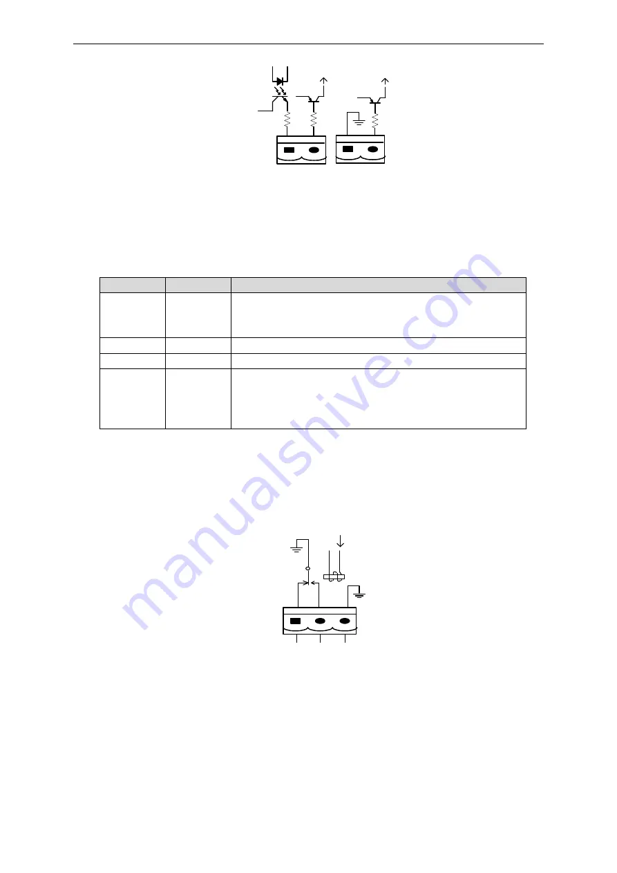
Figure 2-11 Interface BCB
Table 2-5 Description of the BCB interface pins
Pin
Description
Purpose
J6.1
DRV
Information signal about the operating state in bypass mode.
In the bypass operation, the output with 24Vdc (J6.1 - J7.1)
In normal mode, the 0Vdc output (J6.1 - J7.1)
J6.2
CONT
Not used
J7.1
GND
Ground
J7.2
BYP_ONL
The input signal informing about the position of the external
service bypass (NO). Short-circuit of the signal from J7.1
informs the UPS about the closing of the service bypass
switch and switches the UPS to bypass mode.
2.7.5. Output signal - Battery low
The J8 connector of the Dry Contact interface is a low battery information signal. If the battery voltage is
lower than the value that has been configured, then on the J8 output we will receive such information.
There are two types of battery status indication to be used - NO (normally open contact) or NC (normally
closed contact) - change of the contact position means that the battery voltage is low. Below is an
interface description and description of connections.
J8
B
A
T
_
L
O
W
_
N
C
B
A
T
_
L
O
W
_
N
O
G
N
D
Figure 2-12 Interface Bat_Low


