


The AR-SG-4SM-W is a stylish push-button wall plate that
provides control of an An-10 system. Functions include.
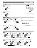
Lights On / Off
Raise / Lower Light Levels
Scene Selection
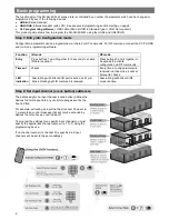
Scene Programming
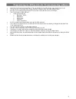
User programming mode for quick and easy scene
setting via infrared, RF (radio) or USB connection to
a PC running CP’s ALC programming software.
Compact design allows installation into standard UK and
European backboxes.
Fascia also available in other finishes.
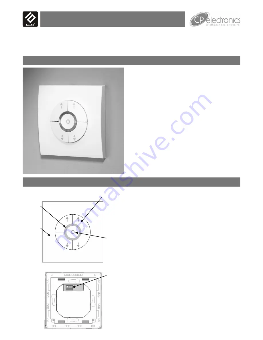
Front features
Off button
Scene buttons
Overview
RF scene plate
AR-SG-4SM-W
Product Guide
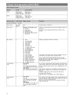
Features
Scene buttons
Four buttons that offer 4 lighting scenes.
Raise and lower function
Use either buttons 1 and 2 to raise the light level.
Use either buttons 3 and 4 to lower the light level.
Off button
Toggle between lights off and last selected Scene.
IR receiver
Receives control and programming commands from an
IR (infrared) handset.
LEDs
The LEDs flash to indicate the that a valid setting has been
received via IR and are also used in the programming of
scenes.
LED ring
IR mode
Fast flashing
RF mode
Slow flashing
USB mode Continuous
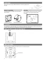
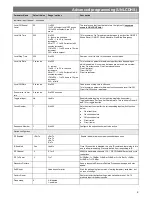
USB port
Under the facia is a micro USB socket for use for
programming via a PC. See page 11 for details.
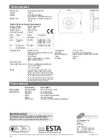
Optional 12Vdc supply terminal
To power the unit from an external supply, connect the
supply to this terminal ensuring correct polarity. Refer to
Technical Data on page 10 for power supply specification.
Back features
Optional
12Vdc
Supply
Terminal
LED ring
Fascia


