background image

Instruction and Operation Manual 

Misprints and technical changes reserved


6.


Options


o


Brake resistors up to 60kW permanent load in enclosure IP 20. Specific possible after previous 
Consulation with TAE. 

o


Overcurrent relays for protection of the brake resistor against thermal overstressing. Overcurrent 
relays with higher rated current on request 
 

6.1


Overcurrent relay 

Rated current in A: 

Part.-No: 


Rated current in A: 

Part.-No: 

0,1 - 0,16 

36770-A2 


1,6 - 2,4 

36770-G2 

0,16 - 0,24 

36770-B2 


2,4 - 4 

36770-H2 

0,24 - 0,4 

36770-C2 


4 - 6 

36770-I2 

0,4 - 0,6 

36770-D2 


6 - 10 

36770-K2 

0,6 - 1 

36770-E2 


10 - 16 

36770-L2 

1 - 1,6 

36770-F2 


16 - 24 

36770-M2 

Bracket for Overcurrent relay: Art.-No. 36770-Z2


6.2


Ultrafast semiconductor fuses 

Use with Braking chopper: 

Fuse value in A A 

Part.-No. Fuse 

Art.-No. Fuse Breaker 3pol 

12262-0F... 

50 

34606-00 

34529-00 

12262-1F... 

63 

34607-00 

34529-00 

12263-AF... 

100 

34609-00 

34529-00 

12263-0F... 

100 

34609-00 

34529-00 

12263-1F... 

125 

34610-00 

34529-00 

12263-2F... 

200 

34621-00 

34529-01 

12264-0F... 

250 

34622-00 

34529-01 

12264-1F... 

355 

34633-00 

34529-02 

12264-2F... 

500 

on request 

34529-03 

7.


Calculation Braking Chopper and Resistor


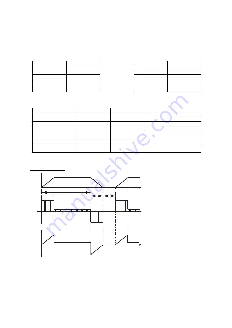
Basis of calculation: 

 Constant Brake torque and 
linear speed reduction 


Example: 

Brake torque 100 Nm 
Max Speed 2400 min-1 
Motor operation time 14 sec. 
Brake time 3 sec. 
Stop 3 sec. 
Chopper voltage 750 V 

n[min

-1

]

P[kW]

M+

[Nm]

M-

[Nm]

t

RUN

= 14 s

M

MAX

P

MAX BRAKE

t

BRAKE

=

3 s

t

OFF

= 3 s

n

max

= 2400 min

-1

n

mittel

=1200 min

-1

0

0

0

100 Nm

t[s]

t[s]

t[s]

25,1 kW

Summary of Contents for BC 2.2 Series

Page 1: ...Brake Chopper BC 2 2 4 2 Instruction and Operation Manual...

Page 2: ...done by qualified personnel The precautions and warnings below must be observed at the operation of the chopper The braking chopper instruction and operation manual do not replace the manual of initia...

Page 3: ...nditions 4 2 2 Technical Data Chopper voltage 1000V 4 3 Connections and Indications 5 3 1 Design 5 3 2 Connectiondiagramm 6 4 Example of Connection 7 5 Dimensions 7 6 Options 8 6 1 Overcurrent relay 8...

Page 4: ...class F without condensation 5 85 relative humidity Environment Base standard DIN EN 60068 2 6 Resonance seach Test specification 5 Hz 13 2 Hz 150 Hz 2mm peak to peak 0 7g Installation height h H 100...

Page 5: ...r BUSS connection BUSS voltage inverter R1 R2 a bimetal relay must be connected in series to the braking resistor This has to be adjusted to the nominal current of the brake resistor see Chapter 4 Exa...

Page 6: ...6 Instruction and Operation Manual Misprints and technical changes reserved 3 2 Connectiondiagramm...

Page 7: ...n If cables between inverter and chopper resp chopper and brake resistor are less than 25 cm they have to be twisted and if they are longer than 25 cm they have to be shielded 5 Dimensions Type B B1 H...

Page 8: ...racket for Overcurrent relay Art No 36770 Z2 6 2 Ultrafast semiconductor fuses Use with Braking chopper Fuse value in A A Part No Fuse Art No Fuse Breaker 3pol 12262 0F 50 34606 00 34529 00 12262 1F 6...

Page 9: ...MS brake load PMAX BRAKE in kW peak load brake chopper tBRAKE in seconds brake time tRUN in seconds motoring operation tBRAKE in seconds regen operation tOFF in seconds stop Calculation Brake Resistor...

Page 10: ...10 Instruction and Operation Manual Misprints and technical changes reserved 8 Connection Diagramm option Master Slave...

Reviews: