CHPA SERIES
D
OC
.01023245
R
EV
.L
THIS
DOCUMENT
IS
THE
PROPERTY
OF
COMMUNICATIONS
&
POWER
INDUSTRIES.
REPRODUCTION
OR
RELEASE
WITHOUT
EXPRESS
PERMISSION
IS
STRICTLY
PROHIBITED
B-3
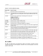
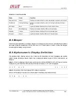
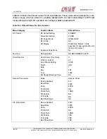
Table B-2. Front Panel LEDs
Name Color Function
Recycle Fault
Green
Flashes to indicate that the unit successfully recycled out of a fault.
Test Mode
Yellow (flashing)
Flashes to indicate that the unit is in Factory Authorized Access
Mode.
RF Inhibit
Red
Lights to indicate that the HPA is in RF Inhibit mode.
Fault
Red (flashing)
Flashes to indicate that the HPA is in Fault state.
Standby
Yellow
Lights to indicate that the HPA is in Standby state.
Transmit
Green
Lights to indicate that the HPA is in Transmit state.
B.4 Beeper
The front panel assembly includes a beeper. The beeper sounds once to indicate that a button
has been pressed successfully. When the HPA is in Fault state or Alarm mode, the beeper
sounds approximately every second.
B.5 Alphanumeric Display Definition
The alphanumeric display area is four lines by 20 characters. All text messages use capital
letters unless otherwise shown. Each line is assigned certain types of HPA information, as
follows:
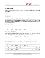
Line 1—This line displays the chosen control point (LOCAL REMOTE, CIF), RF Power Control
mode (ALC), and the time. If the 24-hour format is chosen, A or P will not appear.
C I F A L C
1 1 : 0 0 P
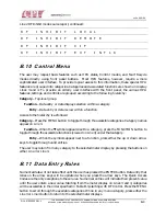
Line 2—In general, this line displays HPA state or sequence.
HPA in HTD state. (Timer shown is the Heater Time Delay countdown timer.)
H T D 3 : 0 0

