CHPA SERIES
B-16
THIS
DOCUMENT
IS
THE
PROPERTY
OF
COMMUNICATIONS
&
POWER
INDUSTRIES.
REPRODUCTION
OR
RELEASE
WITHOUT
EXPRESS
PERMISSION
IS
STRICTLY
PROHIBITED
D
OC
.01023245
R
EV
.L
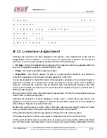
intermodulation products without linearizer. It is best to now finely tune the Phase and
Magnitude controls to assure that the best tuning has been achieved - this is an iterative process,
and some fine tweaking is usually necessary.
B.13 RF Trip Limits/Switch Port Relay Settings
Both RF alarms and faults will be active simultaneously. Alarms provide visual and audible
warnings. In addition to visual and audible warnings, faults cause the CHPA to enter the Fault
state. See Table B-6 for a description of the functions in this category.
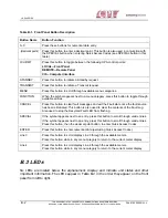
Table B-6. RF Alarms and Faults
Function Name
Possible Entries
Description
High RF Alarm
Numerical entry - format dictated
by the RF Display setting
If the RF output exceeds this limit, the panel
will indicate an alarm condition.
High RF Fault
Numerical entry - format dictated
by the RF Display setting
If the RF output exceeds this limit, the CHPA
enters the Fault state.
Low RF Alarm
Numerical entry - format dictated
by the RF Display setting
If the RF output falls under this limit, the
panel will indicate an alarm condition. This
setting is also used to trigger the Low RF
Relay.
Low RF Fault
Numerical entry - format dictated
by the RF Display setting
If the RF output falls under this limit, the
CHPA enters the Fault state.
High Reflected RF
Fault
Numerical entry - format dictated
by the RF Display setting
If the Reflected RF exceeds this limit, the
CHPA enters the Fault state.
Low RF Relay
Flexible/Rigid
Select either Flexible or Rigid mode
operation for the Low RF relay.
Fault Relay
Fault, Low RF, Sum Fault, ((High
Voltage On) and (NOT RF
Inhibit)), High Voltage ON
The Fault Relay may be reassigned to other
signals as shown.
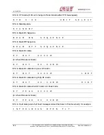
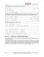
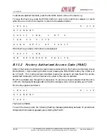
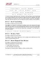
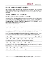
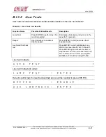
The sample screen for RF Trip Limits is as follows:
L O C A L
1 5 : 2 7
S T A N D B Y
R F T R I P L I M
I T S
t

