CHPA SERIES
D
OC
.01023245
R
EV
.L
THIS
DOCUMENT
IS
THE
PROPERTY
OF
COMMUNICATIONS
&
POWER
INDUSTRIES.
REPRODUCTION
OR
RELEASE
WITHOUT
EXPRESS
PERMISSION
IS
STRICTLY
PROHIBITED
3-7
The CHPA External Interlocks Interface is located at connector J8 on the rear panel of the
CHPA. It is a 9-pin D-type connector, with pin assignments as shown in Table 3-4.
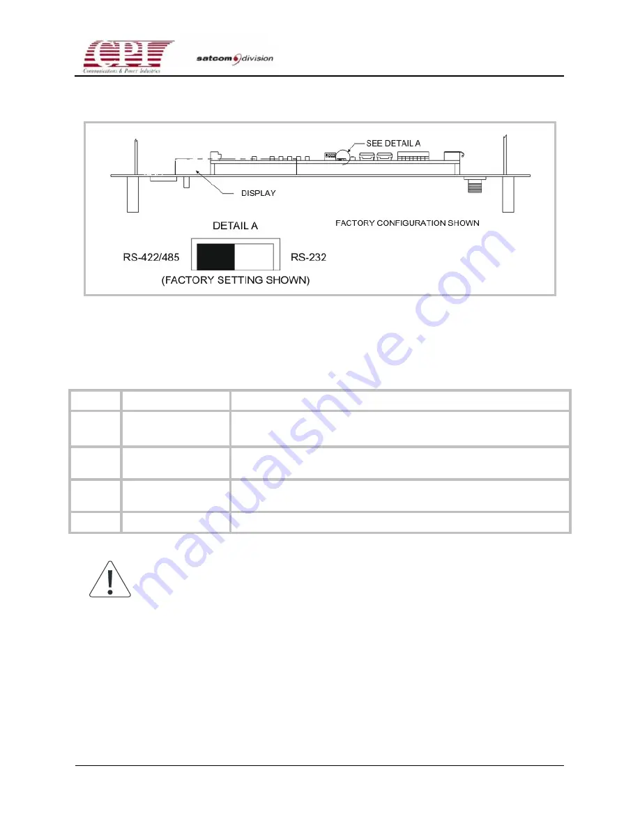
Figure 3-2. Setting Serial Format
Table 3-4. Interlocks Interface Pin Assignments (J8)
Pin #
Signal Name
Remarks
1 External
Interlock
(latching beam off)
Open from Return (pin 2) for External Interlock Fault Latching
2 External
Interlock
Latching
Latching Return
3 External
Interlock
Latching
Open from Return (pin 4) for External RF Inhibit
4
External Interlock
Non-Latching Return
Note: A jumper is factory-installed on this port. When using the External
Interlock Interface, this jumper is not required.


