6.0 OPERATING THE MACHINE
Rover Machines are designed to be simple to operate. Below are diagrams of the Propane and Electric Rover control panels.
Familiarize yourself with the controls and operating procedures for your particular machine before starting any work.
The Start Button
The Start Button should be pressed after disengaging the emergency stop button. After disengaging the E-
Stop button, there is a 10-second delay before starting is possible. When the red light turns on, turn to
start the machine. Upon turning the start button, begin to turn the throttle slowly counterclockwise until
desired RPM is reached.
The Emergency Stop Button
The emergency stop button must be disengaged before starting the machine. When stopping
the machine, turn the throttle down to lower the RPM and depress the Emergency Stop button.
This button should also be depressed in case of emergency necessitating stopping the machine.
The Throttle
The throttle is located on the upper left hand side of the machine frame. When starting the
machine, the throttle must be turned slowly counterclockwise to engage the engine. Continue to
turn the throttle until the machine reaches the desired RPM.
The Tachometer
The tachometer, located on the upper frame of the grinder displays both machine hours and RPM
of the machine. The button located on the right of the face of the tachometer allows toggling
between the machine hours and RPM.
The Joystick Control
To start the Joystick Control, power the controller on by pushing up on the button labeled with
the on/off icon. The screen should light up.
6.2 The CPS Rover Control Panel
Fig.1 The Rover Control Panel
Summary of Contents for Rover VacPac
Page 1: ...Operator s Manual Rover VacPac ...
Page 2: ......
Page 9: ...4 2 Rover Electric Machine Diagram ...
Page 15: ...Fig 2 Joystick Control on CPS Rover The circled portion is the On Off button ...
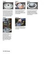
Page 21: ...10 1 Rebuilding Flex Heads ...
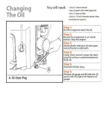
Page 22: ...10 2 Oil Changes ...
Page 23: ......
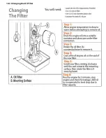
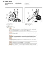
Page 24: ...10 3 Changing the Oil Filter ...
Page 25: ...10 4 Air Filter Service ...
Page 26: ...10 5 Greasing the Ring Gear ...
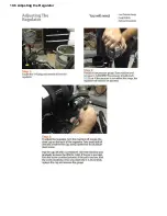
Page 27: ...10 6 Adjusting the Regulator ...
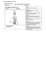
Page 28: ...10 7 Changing the Spark Plugs ...
Page 29: ......


