1550 Inst
Issue 6 05/09/06
23
12. Cutter Height Adjustment
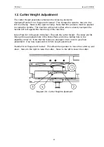
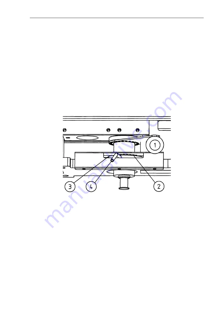
The Cutter Height assembly comprises the following elements:
Clamping Handle [(1) in Diagram 20 below]. This clamps the spindle. Move to the
left to unclamp. Move to the right to clamp. Note that firm pressure must be applied
to clamp the spindle. The machine will be set so that, when correctly clamped, the
handle will rest against the main body of the machine.
Index Plate [(2) in Diagram 20 below]. This sets the cutter height. The index pin fits
through the appropriate hole in the Index Plate, and into a mating hole in the
adjusting collar (3). Note that the holes are arranged in two rows to give finer
adjustment. One hole represents 0.02mm height adjustment.
Handle [(4) in Diagram 20 below]. This allows the operator to move the cutter up and
down. Move to the right to raise the cutter. Move to the left to lower the cutter.
Diagram 20. Cutter Height Adjustment


