1550 Inst
Issue 6 05/09/06
7
6. Machine Controls
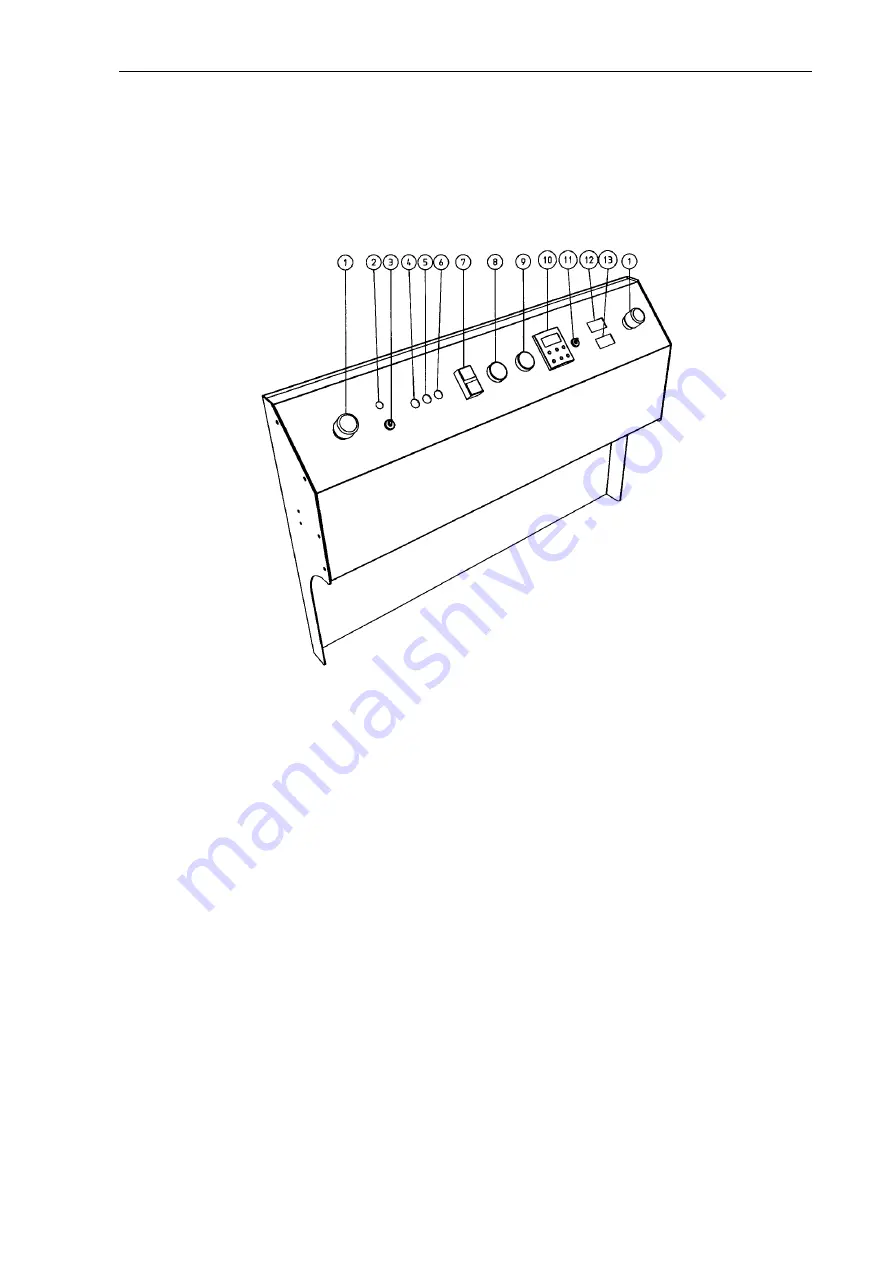
All of the machine controls are located on the front control panel as shown in
Diagram 3 below.
Diagram 3. Machine controls
1.
Emergency Stop Buttons. Disable all machine movements. Push to operate.
Twist buttons to release.
2.
Mains Neon. Illuminates when machine Mains Switch (3) is in the On (I)
position.
3.
Mains Switch. I = On. O = Off. No power is available to the machine controls
unless in the I position.
4.
Fuse–Control. Provides overload protection for the Control Circuit. Rating =
500mAF.
5.
Fuse-Spindle. Provides overload protection for the Spindle Motor. Rating =
2A-T.
6.
Fuse-Transport. Provides overload protection for the Transport Motor.
Rating=5A-T.
7.
Machine Functions On-Off Button. Pressing I switches on Spindle, Transport
and Extraction systems. Pressing O switches these functions off.
8.
Speed Control – Transport. Adjusts Feed Rate of material through machine.
9.
Speed Control – Spindle. Adjusts Spindle speed.
10.
Phase Invertor Display. Provides display of spindle frequency. 50.0Hz =
20,000rpm. 30.0Hz = 14,000rpm. The display can also be used to configure
the phase invertor. This procedure should only be carried out with guidance
from the Technical Staff of the supplier or distributor.


