background image


Understanding LEDs 

 
Refer to the following table for information about LED indicators.  
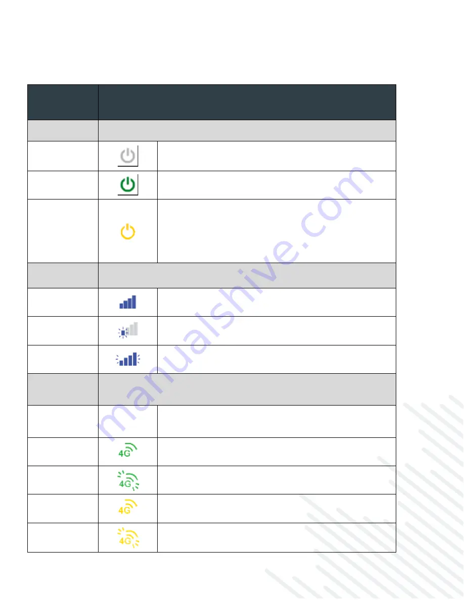
 

Status 

Indicator 

Behavior 

POWER 

The Cradlepoint R1900 must be powered using an approved 9-36V DC power 
source. 


No Light

 = Not receiving power. Check the power 

switch and source connection. 


Green

 = Powered ON. 


Yellow

 = Attention. Log into NCM and use the 

Remote Connect menu to access the router’s NCOS to 
manage any alert.  

o


NOTE: Upon initial installation, the light will 
be yellow until the device is registered in 
NetCloud Manager (NCM). 

SIGNAL 

STRENGTH 

LED bars indicate the modem’s signal strength.  


4 Solid Bars

 = Strongest signal 


1 Blinking Bar

 = Weakest signal (A blinking bar 

indicates half of a bar) 


4 Blinking Bars

 = SIM door is not installed, modem is 

off 

4G LTE 

EMBEDDED 

MODEM 

Indicates information about the embedded 4G LTE modem. 


No Light

 = Modem not connected. 

o


NOTE: You will not be able to see the icon 
when the modem is not connected. 


Solid Green

 = Modem has established an active WAN 

connection. 


Flashing Green

 = Modem is connecting. 


Solid Yellow

 = Modem is not active. 


Flashing Yellow

 = Data connection error. No modem 

connection possible. 

Summary of Contents for R1900 Series

Page 1: ...ntability or fitness for a particular purpose While Cradlepoint has made every effort to ensure this Professional Installation Guide is accurate Cradlepoint disclaims liability for any inaccuracies or omissions that may have occurred and shall not be liable for any adverse results caused in whole or in part by the installer s reliance upon the instructions in this Professional Installation Guide I...

Page 2: ...IAL EXEMPLARY INCIDENTAL CONSEQUENTIAL OR PUNITIVE DAMAGES HOWEVER CAUSED AND UNDER ANY THEORY OF LIABILITY ARISING IN ANY WAY IN CONNECTION WITH YOUR INSTALLATION ACTIVITIES EVEN IF CRADLEPOINT HAS BEEN ADVISED OF THE POSSIBILITY OF SUCH DAMAGE SOME JURISDICTIONS SUCH AS THE STATE OF NEW JERSEY DO NOT ALLOW THE EXCLUSION OR LIMITATION OF INCIDENTAL OR CONSEQUENTIAL DAMAGES SO THE ABOVE EXCLUSION ...

Page 3: ...ller Network 2 R1900 Series Router Models 4 Before You Begin 4 Location Considerations 4 SIM Card for Wireless Connectivity 4 Router Communication and Data Usage 4 Required Tools for Setup 5 Setup 5 STEP 1 Check box for contents 5 STEP 2 Remove the SIM door 5 STEP 3 Insert an activated 4FF sized SIM into the router 6 STEP 4 Reinstall the SIM door 6 STEP 5 OPTIONAL Connect to an RX30 managed access...

Page 4: ...device to become too hot to safely touch Mount in locations compliant with the Safety Regulatory and Warranty guide included in the product shipping box For mobile installations refer to the Vehicle Installation Guide for Mobile Routers for more information IMPORTANT The R1900 Series router requires increased separation distances in relation to other networking hardware Therefore Cradlepoint requi...

Page 5: ...onal screws o Zip ties Setup Refer to the following for general setup instructions STEP 1 Check box for contents Prior to having the R1900 router installed open the box and ensure that all items are present You should have received the following 1 R1900 series router 1 3 meter 2x2 Power and GPIO cable 4 M4 screws nuts and washers 1 Mounting template 1 Quick Start Reference sheet 1 Safety Warranty ...

Page 6: ...nto the router Insert an activated 4FF SIM card into the SIM1 slot contacts down notch in The SIM card will click into place Optionally insert an active 4FF SIM into the SIM2 slot with the same orientation STEP 4 Reinstall the SIM door Replace the SIM cover and secure with the SIM door screws ...

Page 7: ...tely or through a third party vendor Refer to the Cradlepoint Antenna webpage for more information and options NOTE Only use remote or cabled out x in 1 antennas Paddle antennas are not recommended for optimal performance Refer to the Vehicle Installation Guide for Mobile Routers for antenna setup best practices STEP 7 Mount the router The R1900 series router may be mounted in a number of ways and...

Page 8: ... connectivity you will need to power up the router first access your NetCloud Manager account and then complete the setup STEP 9 Power up the router The 4 pin GPIO cable is configured to allow for using a 4 wire GPIO cable to hardwire power for DC connections or for using GPIO Refer to the following for pin configuration Insert the 4 pin end of the power adapter into the 4 pin port on the router e...

Page 9: ...the vehicle chassis 5 White GPIO3 LVTTL compatible protected to 36V DC input 6 Blue GPIO2 LVTTL compatible protected to 36V DC input 7 Yellow GPIO1 LVTTL compatible protected to 36V DC input 8 Orange Ignition Sense Provides option to power up when vehicle ignition is on STEP 10 Activate the router through NetCloud Manager Activate your R1900 series router through NetCloud Manager NCM Your router i...

Page 10: ...llow until the device is registered in NetCloud Manager NCM SIGNAL STRENGTH LED bars indicate the modem s signal strength 4 Solid Bars Strongest signal 1 Blinking Bar Weakest signal A blinking bar indicates half of a bar 4 Blinking Bars SIM door is not installed modem is off 4G LTE EMBEDDED MODEM Indicates information about the embedded 4G LTE modem No Light Modem not connected o NOTE You will not...

Page 11: ...connected Wi Fi BROADCAST Indicates activity on the Wi Fi broadcast for both 2 4 and 5 GHz bands No Light Wi Fi is not operating Blue Wi Fi is on and operating normally LAN ACTIVITY Indicates an active LAN connection NOTE Only one LAN connection will be active at a time No Light LAN is not connected or is not currently active Flashing Green Active LAN connection GPS Indicates the status of the GPS...

Page 12: ...g process You must be physically co located with the device to do this If there is no Internet connection refer to the following No Internet or Connection Issues NCOS How to Configure WAN Interfaces Once the device connects to the Internet ensure that desired functionality is working appropriately through NCM Troubleshooting Customer Support Customer Community Help and Support Cradlepoint Customer...

Page 13: ...permitted for devices in the band 5725 5850 MHz shall be such that the equipment still complies with the e i r p limits as appropriate detachable antenna only INDUSTRY CANADA RADIATION EXPOSURE STATEMENT This equipment complies with IC radiation exposure limits set forth for an uncontrolled environment This equipment should be installed and operated with minimum distance of 21 cm between the radia...

Page 14: ...e failure to transmit or receive data could result in property damage or loss or personal inj ury of any kind including death to the user or to any other party Cradlepoint expressly disclaims liability for damages of any kind resulting from a delays errors or losses of any data transmitted or received using the device or b any failure of the device to transmit or receive such data For proper and s...

Page 15: ...tCloud credentials 2 Follow the step by step instructions in Cradlepoint Verify to set up your device 3 To configure and manage your devices visit NetCloud Manager at cradlepointecm com 4 Find more detailed instructions at cradlepoint com r1900 start Access the Community for best practice documentation at customer cradlepoint com ...

Reviews: